S-4: Difference between revisions
Jump to navigation
Jump to search
No edit summary |
|||
| Line 1: | Line 1: | ||
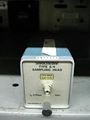
The S-4 was designed by George Frye and [[introduced in 1968]]. | {{Plugin Sidebar | | ||
title=Tektronix S-4 | | |||
summary=Sampling Head | | |||
image=s4-crop.jpg | | |||
caption=S-4 head | | |||
series=[[:Category:Sampling plugins|7000/S3 series Sampling Plugins]] | | |||
years=1968 – ? | | |||
manuals= | |||
* [http://w140.com/tek_s4.pdf Tektronix S-4 Manual, copyright 1969 (PDF)] | |||
* [http://w140.com/tek_S4_1985.pdf Tektronix S-4 Manual, revised 1985 (PDF)] | |||
* [http://w140.com/frye_s4_gate.pdf George Frye's Explanation of S-4 sampler in October 1968 Service Scope (PDF)] | |||
}} | |||
The S-4 was designed by George Frye and [[introduced in 1968]]. It is the fastest of the S-series plug-in samplers. (An interesting comparison of different sampling heads is found in [http://www.picosecond.com/objects/AN-02a.pdf "AN-3042a, Revision 1, 2/89"].) | |||
The S4 sampling gate is based upon a traveling wave trapped-charge transmission line in which the sampling window is set by the propagation time of pulse edge through a thick-film transmission line. This technique requires only a sharp pulse edge rather than a precise pulse width, which is harder to generate. | The S4 sampling gate is based upon a traveling wave trapped-charge transmission line in which the sampling window is set by the propagation time of pulse edge through a thick-film transmission line. This technique requires only a sharp pulse edge rather than a precise pulse width, which is harder to generate. | ||
The sampling diodes are housed in a special coaxial connector that provides a high bandwidth signal path. | The sampling diodes are housed in a special coaxial connector that provides a high bandwidth signal path. | ||
* | ==Specifications== | ||
* | |||
* | * Rise time: 25 ps | ||
* Bandwidth: 14.5 GHz | |||
* Input impedance: 50 Ω (SMA port) | |||
* Noise: < 5 mV | |||
* Provides a trigger pickoff signal for internal triggering | |||
==Pictures== | |||
<gallery> | <gallery> | ||
Image:Tek s4.jpg | Image:Tek s4.jpg | ||
| Line 14: | Line 32: | ||
Image:S4 schem.png|Schematic | Image:S4 schem.png|Schematic | ||
</gallery> | </gallery> | ||
[[Category:7000 and 3S series sampling heads]] | |||
Revision as of 07:31, 18 May 2014

The S-4 was designed by George Frye and introduced in 1968. It is the fastest of the S-series plug-in samplers. (An interesting comparison of different sampling heads is found in "AN-3042a, Revision 1, 2/89".)
The S4 sampling gate is based upon a traveling wave trapped-charge transmission line in which the sampling window is set by the propagation time of pulse edge through a thick-film transmission line. This technique requires only a sharp pulse edge rather than a precise pulse width, which is harder to generate. The sampling diodes are housed in a special coaxial connector that provides a high bandwidth signal path.
Specifications
- Rise time: 25 ps
- Bandwidth: 14.5 GHz
- Input impedance: 50 Ω (SMA port)
- Noise: < 5 mV
- Provides a trigger pickoff signal for internal triggering
Pictures
-
-
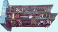
Top view of the S4 plug-in
-
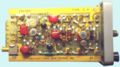
Left view
-
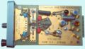
Right view
-
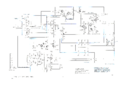
Schematic


