TM503: Difference between revisions
No edit summary |
No edit summary |
||
| Line 20: | Line 20: | ||
* [http://www.amplifier.cd/Test_Equipment/Tektronix/Tektronix_500/TM503B/TM503B.html TM503B @ amplifier.cd] | * [http://www.amplifier.cd/Test_Equipment/Tektronix/Tektronix_500/TM503B/TM503B.html TM503B @ amplifier.cd] | ||
* [https://paulcarbone.com/blog/tektronix-tm-503-repair/ TM503 repair @ paulcarbone.com] | * [https://paulcarbone.com/blog/tektronix-tm-503-repair/ TM503 repair @ paulcarbone.com] | ||
* [https://www.youtube.com/watch?v=VkNRUI_QtWo Tektronix TM503 Mainframe Repair] by NFM @ YouTube | * [https://www.youtube.com/watch?v=VkNRUI_QtWo Tektronix TM503 Mainframe Repair] by NFM @ YouTube (replacement PCBs) | ||
* [https://www.electronicdesign.com/technologies/test-measurement/article/21137778/the-tektronix-function-generator-teardown The Tektronix Function Generator Teardown] - Paul Rako @ electronicdesign.com | * [https://www.electronicdesign.com/technologies/test-measurement/article/21137778/the-tektronix-function-generator-teardown The Tektronix Function Generator Teardown] - Paul Rako @ electronicdesign.com | ||
Revision as of 02:13, 6 September 2021

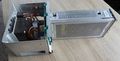
The Tektronix TM503 is a three-bay mainframe for the TM500 system. All bays are low-power. It has a swivelling carrying handle.
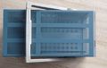
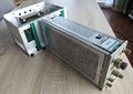
The TM503B also allows the power supply/backplane part to be removed from the case so that modules to be repaired on the bench without using extenders (see link below). It also has openings for the TM5000 GPIB feature, but not the connectors nor the power good signal for TM5000 plugins.
Option 2
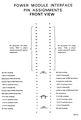
Option 2 adds internal pin headers for each slot as well as rear 50-pin and BNC connectors, allowing for custom wiring to, from and between plugins.
On the standard TM503, cutouts for three BNC sockets have been made in the rear frame, meaning that the user only needs to drill holes in the rear cover plate to install the sockets.
Option 7
Option 7 adds barrier keys (214-1593-02) and connections on the rear interface to allow connections between the DC502-option7 to either a TR502 or a SW503 such that the center or marker frequency of a sweep can be read of the DC502.
Key Specifications
- please add
Links
- TM503B @ amplifier.cd
- TM503 repair @ paulcarbone.com
- Tektronix TM503 Mainframe Repair by NFM @ YouTube (replacement PCBs)
- The Tektronix Function Generator Teardown - Paul Rako @ electronicdesign.com
Pictures
-

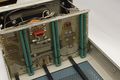
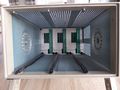
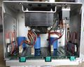
TM503 inside
-
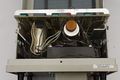
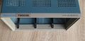
TM503 backplane
-

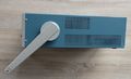
TM503 PSU
-
-
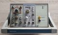
TM503B Front view with plugins
-
-
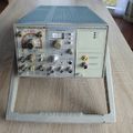
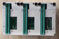
TM503B Front view without plugins
-
TM503B internal view
-
TM503B side view
-
TM503B rear view
-
TM503B top view
-
TM503B bottom view
-
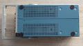
TM503B power supply front view
-
TM503B power supply top view
-

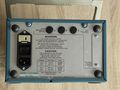
TM503B power supply rear view
-
Using a TM503B for repairing plugins
-
Using a TM503B for repairing plugins


Schematics
-
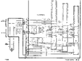
TM503 schematic
-
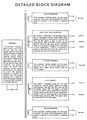
Block diagram
-
Interface connectors


