1S1: Difference between revisions
No edit summary |
No edit summary |
||
| Line 1: | Line 1: | ||
{{Plugin Sidebar| | |||
title=Tektronix 1S1| | |||
summary=Sampling system| | |||
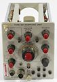
image=1s1_front.jpg | | |||
caption=1S1 front view| | |||
years=1965 – 1973| | |||
type=Combined| | |||
series=[[500-series scopes]]| | |||
manuals= | |||
* [http://bama.edebris.com/download/tek/1s1/1s1.djvu Tektronix 1S1 Manual (DjVu)] | |||
* [http://w140.com/1s1.pdf Tektronix 1S1 Manual (PDF)] | |||
}} | |||
The 1S1 is a [[sampling oscilloscope|sampling]] plug-in for [[500-series scopes]]. | The 1S1 is a [[sampling oscilloscope|sampling]] plug-in for [[500-series scopes]]. | ||
It is essentially one channel of a sampling unit and a timing unit from a [[661]]. | |||
It has its own trigger and timebase. | It is essentially one channel of a sampling unit and a timing unit from a [[661]]. It has its own trigger and timebase. | ||
The oscilloscope's timebase is usually set to a relatively slow sweep rate when using a 1S1. | |||
Alternatively, the sweep on the oscilloscope can be free-run, | The oscilloscope's timebase is usually set to a relatively slow sweep rate when using a 1S1. Alternatively, the sweep on the oscilloscope can be free-run, | ||
and the horizontal voltage from the oscilloscope can be used to control the 1S1, as described below. | and the horizontal voltage from the oscilloscope can be used to control the 1S1, as described below. | ||
The 1S1 has a 50 | |||
The plug-in supplies power (+ | The 1S1 has a 50 Ω [[Connectors#GR-874|GR-874]] connector for signal input. The plug-in supplies power (+100 V and -12.6 V) to active probes such as the [[P6032]] cathode follower probe. | ||
The 1S1 can operate in normal self-swept mode or an external sweep signal can be applied to the 1S1. | The 1S1 can operate in normal self-swept mode or an external sweep signal can be applied to the 1S1. | ||
| Line 22: | Line 35: | ||
For example, one might want to know, when testing a logic gate, what is the propagation delay | For example, one might want to know, when testing a logic gate, what is the propagation delay | ||
such that 99.9% of the transitions happen faster than this. | such that 99.9% of the transitions happen faster than this. | ||
The horizontal-in voltage can also be produced, in "manual" mode, by setting a knob on the 1S1. | The horizontal-in voltage can also be produced, in "manual" mode, by setting a knob on the 1S1. | ||
The sampler in the 1S1 is quite different from the sampler in the [[1S2]]. | The sampler in the 1S1 is quite different from the sampler in the [[1S2]]. The 1S1 uses a [[sampling diodes|four-diode]] sampling bridge, terminated within the 1S1. The 1S2 uses a two-diode feed-through sampler, typical for TDR instruments. | ||
The 1S1 uses a [[sampling diodes|four-diode]] | |||
sampling bridge, terminated within the 1S1. The 1S2 uses a two-diode feed-through sampler, typical for | |||
TDR instruments. | |||
Type 1S1 was [[introduced in 1965]] and sold through 1973. | Type 1S1 was [[introduced in 1965]] and sold through 1973. | ||
==Pictures== | |||
<gallery> | <gallery> | ||
| Line 39: | Line 49: | ||
Image:1s1 block.jpg|block diagram | Image:1s1 block.jpg|block diagram | ||
</gallery> | </gallery> | ||
[[Category:Sampling plugins]] | |||
[[Category:500 series vertical plugins]] | |||
Revision as of 08:04, 9 May 2014

The 1S1 is a sampling plug-in for 500-series scopes.
It is essentially one channel of a sampling unit and a timing unit from a 661. It has its own trigger and timebase.
The oscilloscope's timebase is usually set to a relatively slow sweep rate when using a 1S1. Alternatively, the sweep on the oscilloscope can be free-run, and the horizontal voltage from the oscilloscope can be used to control the 1S1, as described below.
The 1S1 has a 50 Ω GR-874 connector for signal input. The plug-in supplies power (+100 V and -12.6 V) to active probes such as the P6032 cathode follower probe.
The 1S1 can operate in normal self-swept mode or an external sweep signal can be applied to the 1S1. With the 1S1's internal sweep disabled, the horizontal-in and vertical-out connections can be used so the the 1S1 acts as a lookup table, a mapping of x to y, a function. The 661 also has this capability, in its "A vert/B horiz" mode, which is like X-Y mode for a sampler. In this mode, the horizontal-in voltage controls to the time after the trigger event when the sample should be taken, and the vertical-out voltage corresponds to the voltage measured at that instant. This allows a waveform to be digitized using an arbitrarily slow DAC to generate the horizontal voltage and ADC to read the sampled output. But perhaps more importantly, by setting a constant horizontal-in voltage, it allows the output signal at one equivalent time instant to be processed in the time domain. For example, this allows the voltage to be low-pass filtered, so that it can be more accurately measured. The other reason why one might want a signal that consists of multiple sequential measurements of the same equivalent-time instant is that statistics can be calculated on these observations. For example, one might want to know, when testing a logic gate, what is the propagation delay such that 99.9% of the transitions happen faster than this.
The horizontal-in voltage can also be produced, in "manual" mode, by setting a knob on the 1S1.
The sampler in the 1S1 is quite different from the sampler in the 1S2. The 1S1 uses a four-diode sampling bridge, terminated within the 1S1. The 1S2 uses a two-diode feed-through sampler, typical for TDR instruments.
Type 1S1 was introduced in 1965 and sold through 1973.
Pictures
-
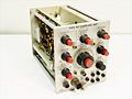
front view
-
-
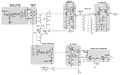
block diagram

