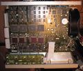
TDS540
The Tektronix TDS540 is a 500 MHz, 1 GS/s quad-channel digital scope introduced in 1992.
The TDS540 uses an amplifier IC, U1000, U1200, U1300, and U1400, part number 155-0378-00, which is a packaging of the M377.
Key Specifications
| Bandwidth | 500 MHz |
|---|---|
| Rise time | 700 ps |
| Sample rate | 1 GS/s (only 1 ch ) / 500 MS/s (only 2 ch) / 250 MS/s (all ch) |
| Time base | 500 ps/Div to 10 s/Div |
| Deflection | 2 mV/Div to 200 mV/Div (Opt. 1D: 1 mV/Div to 100 mV/Div) |
| Resolution | 8 bits / 12 bits (HI-RES Mode) |
| Record length | 500 to 15 k points ( Opt. 1M: 50 k points) |
| Input impedance | 1 MΩ / 50 Ω |
| Interface | GPIB standard |
| Options 13 |
|
Software
- TDS540 V1.3 Field Adjustment Software (ZIP)
- TDS540 V1.4 Field Adjustment Software 063-0935-xx (ZIP)
- TDS540/540A V1.4 Field Adjustment Software (ZIP)
- TDS540/540A V1.6 Field Adjustment Software (ZIP)
- TDS540/540A V1.11 Field Adjustment Software (ZIP)
- TDS540B Field Adjustment Software 063-2601-00 (ZIP)
- TDS540C Field Adjustment Software 063-2774-01 (ZIP)
- TDS540C/540D V1.129 Field Adjustment Software (ZIP)
- TDS540C/540D V1.129 Field Adjustment Software 063-3289-01 (ZIP)
- Waveform Converter For Oscilloscopes 066-0002-00 (ZIP)
- AWE Drivers For Tektronix Oscilloscopes 066-0087-00 (ZIP)
- File Transfer Utility From TDS Scope To PC 066-0104-00 (ZIP)
- Telecom Test and I-Pattern Software TTiP 066-0119-00 (ZIP)
- Enhanced Printing Utility for TDS Family 066-0125-00 (ZIP)
- TDS runtime Environment TDSRTE1 066-0127-00 (ZIP)
- Tektronix TDS500C/700C Custom Masks 066-0165-00 (ZIP)
- WFM to ASCII Waveform Converter - UNIX Version For Sun Spark Stations 066-0176-00 (ZIP)
- Hardcopy from TDS to PC Using HPIP 82335B Interface Card 066-0177-00 (ZIP)
- Example Program To Get Crossing Levels 066-0178-00 (ZIP)
- TDS ISF File To CSV File Conversion Utility 066-0179-00 (ZIP)
- TDS Sandisk Hard Disk Patch Utility 066-0183-00 (ZIP) 500 700
- Transfer 2 Byte Data From TDS Oscilloscopes QuickBasic 066-0188-00 (ZIP)
- TDS Waveform Logging Sample Program 066-0194-00 (ZIP)
- Load TDS Floppy MathCAD Files Into MathCAD 066-0196-00 (ZIP)
- Transfer TDS Hardcopy Screens To PC Via GPIB 066-0197-00 (ZIP)
- Transfer Setups Between TDS Oscilloscopes 066-0198-00 (ZIP)
- VB Program To Capture TDS Extended Waveforms 066-0200-00 (ZIP)
- TDS Series WFM File Formatter 066-0489-00 (ZIP)
- TDS Family Programming Examples Software 063-1134-00 V1.2 (ZIP)
- Telecommunications Option for TDS Oscilloscopes 066-0201-00 (ZIP)
Options
- 05 - Video Trigger
- 13 - RS-232/CENTRONICS HARDCOPY INTERFACE.
- 1K - K420 Oscilloscope Cart without power strip
- 1M - 50k Memory Length
- 1R - Rackmount
- 23 - Add two each P6205 Active Probes
- 25 - Add P6563A, four SMD probes
- 2F - ADVANCED DSP MATH
Repair issues
A common failure reason on early TDS-family scopes are surface-mounted capacitors leaking corrosive electrolyte.
-
Crusty solder joint of surface-mounted electrolytic capacitor. It is an alarm sign.
Pictures
-
-
-
-
SMD caps recapped Acquisition-Board "A10"
-
Option 05 Internal Parts
-
Option HD Internal Parts, 2.5" Disk Version
-
Option HD Internal Parts, PCMCIA Disk Version
Part numbers of included PCB by TDS540
| Part No | Description | Module numbers |
|---|---|---|
| 672-1476-0x | Acquisition board | A10 |
| 672-2045-0x | Acquisition board (1M Option) | A10 |
| 671-1477-01/02 | DRAM/CPU/Display board (1M Option) | A11 |
| 671-2002-01/02 | DRAM/CPU/Display board | A11 |
| 614-0890-00 | Front panel assembly | A12 |
| 614-0896-00/01 | Front panel assembly | A12 |
| 671-1701-00/01 | Firmware board | A13 |
| 671-1568-00 | D1 Bus | A14 |
| 119-4092-0x | Attenuator assembly | A15 |
| 119-3371-0x | Power supply unit | A16 |
| 119-4415-0x | Power supply unit | A16 |
| 640-0071-00/01 | CRT Display assembly | A20 |
Assembly part numbers
| Assy | Description | TDS540 P/N | TDS540A P/N | TDS540B P/N | TDS540C P/N | TDS540D P/N |
|---|---|---|---|---|---|---|
| A10 | Acquisition board | 672-1476-0x | 672-1408-xx | - | 671-4039-01 | |
| A10 | Acquisition board (1M Opt.) | - | - | - | 671-4041-00 | |
| A11 | DRAM/CPU/Display board | 671-2002-01/02 | 671-2771-xx | - | 671-4002-00 | |
| A11 | DRAM/CPU/Display board | 671-1477-01/02(1M Opt.) | - | - | 671-4171-00 | |
| A12 | Front panel assembly | - | 614-2469-xx | - | 614-0935-03 | |
| A12 | Front panel assembly | - | - | - | 614-0937-02 | |
| A13 | Firmware board | 671-1701-00/01 | - | - | - | |
| A14 | D1 Bus | 671-1568-00 | 671-2846-xx | - | 671-2847-00 | |
| A14 | D1 Bus (Opt. 05) | - | - | - | 671-2848-00 | |
| A15 | Attenuator assembly | 119-4092-0x | - | - | - | |
| A16 | Power supply unit | 119-3371-0x | - | - | 620-0063-04 | |
| A16 | Power supply unit | 119-4415-0x | - | - | - | |
| A20 | CRT Display assembly | 640-0071-00/01 | 640-0071-xx | 640-0071-06 | 640-0071-06 | - |
| A23 | RS232/Centronics assembly | 640-2437-00 | 640-2437-00 | 640-2437-00 | 640-2437-00 | - |


