067-0587-02: Difference between revisions
mNo edit summary |
m (Capitolize sidebar summary & Caption) |
||
| (31 intermediate revisions by 5 users not shown) | |||
| Line 1: | Line 1: | ||
{{Plugin Sidebar | {{Plugin Sidebar | ||
|manufacturer=Tektronix | |||
summary=Calibration Fixture | | |type=067-0587-02 | ||
image=Tek-067-0587-02 front.jpg | | |summary=7000 Series Calibration Fixture | ||
caption=067-0587-02 | |image=Tek-067-0587-02 front.jpg | ||
series= | |caption=067-0587-02 Calibration Fixture, Front View | ||
introduced=1979 | | |series=7000-series scopes | ||
discontinued=(?) | | |introduced=1979 | ||
manuals= | |discontinued=(?) | ||
* [ | |designers=Art Metz | ||
|manuals= | |||
* [[Media:070-2427-00.pdf | Tektronix 067-0587-02 Manual]] | |||
* [[Media:070-6178-00.pdf | Product Modification Supplement]] | |||
}} | }} | ||
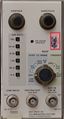
The '''Tektronix 067-0587-02''' is a signal standardizer (calibration) plug-in for [[7000-series scopes]]. | The '''Tektronix 067-0587-02''' is a signal standardizer (calibration) plug-in for [[7000-series scopes]], especially the 1 GHz [[7104]] mainframe. | ||
It is a complete redesign of the [[067-0587-01]] standardizer. It provides a calibrated staircase at 1 line/Div in Gain mode, a fast-rising pulse in Step Resp mode, | It is a complete redesign of the [[067-0587-01]] standardizer. It provides a calibrated staircase at 1 line/Div in Gain mode, a fast-rising pulse in Step Resp mode, an input for a CW signal to test bandwidth, and an input for a common mode test signal. The 067-0587-02 was designed by [[Art Metz]]. A modification kit was available to make it a [[067-0587-10]]. | ||
{{BeginSpecs}} | {{BeginSpecs}} | ||
{{ | {{SpecGroup | GAIN mode }} | ||
{{Spec | Staircase accuracy | ± 0.3% in ± 3 Div, ± 0.5% in ± 4 Div, Linearity ± 0.2% of 10 Div }} | {{Spec | Staircase accuracy | ± 0.3% in ± 3 Div, ± 0.5% in ± 4 Div, Linearity ± 0.2% of 10 Div }} | ||
{{ | {{SpecGroup | STEP RESP mode }} | ||
{{Spec | Amplitude | 2 to 10 Div }} | {{Spec | Amplitude | 2 to 10 Div }} | ||
{{Spec | Position | Top at least ±5 Div from center of screen }} | {{Spec | Position | Top at least ±5 Div from center of screen }} | ||
| Line 22: | Line 25: | ||
{{Spec | Repetition rate | 10 Hz to 1 MHz in decade steps, 0.1 %}} | {{Spec | Repetition rate | 10 Hz to 1 MHz in decade steps, 0.1 %}} | ||
{{Spec | Pretrig Out | 0.5 V into 50 Ω, 55 to 95 ns lead time (internally variable) }} | {{Spec | Pretrig Out | 0.5 V into 50 Ω, 55 to 95 ns lead time (internally variable) }} | ||
{{ | {{SpecGroup | FREQ RESP mode }} | ||
{{Spec | Input impedance | 50 Ω }} | {{Spec | Input impedance | 50 Ω }} | ||
{{Spec | Input range | 0.5 to 1 V<sub>p-p</sub> }} | {{Spec | Input range | 0.5 to 1 V<sub>p-p</sub> }} | ||
{{Spec | Flatness | ± 3% from 3 MHz to 1 GHz }} | {{Spec | Flatness | ± 3% from 3 MHz to 1 GHz }} | ||
{{EndSpecs}} | {{EndSpecs}} | ||
==Links== | |||
* [http://amplifier.cd/Test_Equipment/Tektronix/Tektronix_7000_series_special/calibration-fixture.htm 067-0587-02 @ amplifier.cd] (comparing -01 and -02, lots of pictures, text in German) | |||
* [https://www.youtube.com/watch?v=bIZYGPp4WRY Tektronix Calibration Fixtures and Standardizers For 7K Frames] @ Zenwizard Studios YouTube | |||
* [[Patent US 4400234A]] (Elastomer switch) | |||
{{Documents|Link=067-0587-02}} | |||
==Internals== | ==Internals== | ||
Internal signals are derived from a 1 MHz oscillator with selectable decade divisions down to 10 Hz repetition. | |||
The clock is delayed, amplified and limited, then fed to a Schottky-diode based pulse shaper with L-C compensating networks. The output pulse has a rise time of max. 150 picoseconds with less than 2% aberrations. | |||
The staircase generator for Gain mode is implemented using a 4 bit counter and multiplexer. The 0-volt step (No. 6) is held for five counts, producing a brighter trace to allow easy alignment with the center of the screen. | |||
For bandwidth measurements, there is a leveler circuit with a [[155-0183-00|differential diode detector]] controlling an amplifier's gain in an AGC loop. '''NB:''' The response is not specified below 3 MHz. | |||
The 067-0587-02 is based on a number of Tektronix custom ICs from the 1 GHz [[7104]] scope generation, such as the [[155-0160-00|155-0160-00 trigger amplifier + source select chip]] and the [[155-0175-00|155-0175-00 trigger amplifier chip]]. | The 067-0587-02 is based on a number of Tektronix custom ICs from the 1 GHz [[7104]] scope generation, such as the [[155-0160-00|155-0160-00 trigger amplifier + source select chip]] and the [[155-0175-00|155-0175-00 trigger amplifier chip]]. | ||
The mode selector switch is a special elastomer-based cam switch. The manual warns that while it can be cleaned if proper procedure is followed (note some screws are labelled "do not remove" on the cover!), only at the factory can (could ...) it be repaired/re-assembled completely. | The mode selector switch is a special elastomer-based cam switch. The manual warns that while it can be cleaned if proper procedure is followed (note some screws are labelled "do not remove" on the cover!), only at the factory can (could ...) it be repaired/re-assembled completely. A [[Media:7104_maintenance.pdf|Tek-internal introduction to 7104 maintenance]] discusses this switch in detail. | ||
==Pictures== | ==Pictures== | ||
<gallery> | <gallery> | ||
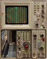
Tek-067-0587-02 front.jpg | 067-0587-02 front view | |||
Tek-067-0587-02 left.jpg | 067-0587-02 left side (cam switch assembly on bottom left) | |||
Tek-067-0587-02 right.jpg | 067-0587-02 right side (modified as [[067-0587-10]], note extra switch and resistor in top middle area of PCB) | |||
Tek-067-0587-02-gain-v.jpg | 067-0587-02 in gain mode, vertical slot (horizontal lines) | |||
Tek-067-0587-02-gain-h.jpg | 067-0587-02 in gain mode, horizontal slot (vertical lines) | |||
Tek7104-ristetime-1000hz.jpg | Rise time measurement of [[7104]] mainframe, 1000 Hz repetition rate. t<sub>r</sub>=240 ps (corrected for 150 ps fixture rise time = 190 ps equ. 1.8 GHz) | |||
067-0587-02 rise and fall 1.jpg | Rise and fall time of 067-0587-02 shown on separate timebases in 7104 (STEP RESP+) | |||
067-0587-02 rise and fall 2.jpg | Rise and fall time of 067-0587-02 shown on separate timebases in 7104 (STEP RESP+), expanded scale | |||
</gallery> | </gallery> | ||
[[Category:7000 series | ==Components== | ||
{{Parts|067-0587-02}} | |||
[[Category:7000 series test and calibration plugins]] | |||
Latest revision as of 21:11, 15 November 2023

The Tektronix 067-0587-02 is a signal standardizer (calibration) plug-in for 7000-series scopes, especially the 1 GHz 7104 mainframe. It is a complete redesign of the 067-0587-01 standardizer. It provides a calibrated staircase at 1 line/Div in Gain mode, a fast-rising pulse in Step Resp mode, an input for a CW signal to test bandwidth, and an input for a common mode test signal. The 067-0587-02 was designed by Art Metz. A modification kit was available to make it a 067-0587-10.
Key Specifications
| — GAIN mode — | |
| Staircase accuracy | ± 0.3% in ± 3 Div, ± 0.5% in ± 4 Div, Linearity ± 0.2% of 10 Div |
| — STEP RESP mode — | |
| Amplitude | 2 to 10 Div |
| Position | Top at least ±5 Div from center of screen |
| Rise time | < 150 ps |
| Repetition rate | 10 Hz to 1 MHz in decade steps, 0.1 % |
| Pretrig Out | 0.5 V into 50 Ω, 55 to 95 ns lead time (internally variable) |
| — FREQ RESP mode — | |
| Input impedance | 50 Ω |
| Input range | 0.5 to 1 Vp-p |
| Flatness | ± 3% from 3 MHz to 1 GHz |
Links
- 067-0587-02 @ amplifier.cd (comparing -01 and -02, lots of pictures, text in German)
- Tektronix Calibration Fixtures and Standardizers For 7K Frames @ Zenwizard Studios YouTube
- Patent US 4400234A (Elastomer switch)
Documents Referencing 067-0587-02
| Document | Class | Title | Authors | Year | Links |
|---|---|---|---|---|---|
| Tekscope 1979 V11 N1.pdf | Article | A New Calibration Fixture for the 7000-Series | Art Metz | 1979 | 067-0587-02 |
Internals
Internal signals are derived from a 1 MHz oscillator with selectable decade divisions down to 10 Hz repetition.
The clock is delayed, amplified and limited, then fed to a Schottky-diode based pulse shaper with L-C compensating networks. The output pulse has a rise time of max. 150 picoseconds with less than 2% aberrations.
The staircase generator for Gain mode is implemented using a 4 bit counter and multiplexer. The 0-volt step (No. 6) is held for five counts, producing a brighter trace to allow easy alignment with the center of the screen.
For bandwidth measurements, there is a leveler circuit with a differential diode detector controlling an amplifier's gain in an AGC loop. NB: The response is not specified below 3 MHz.
The 067-0587-02 is based on a number of Tektronix custom ICs from the 1 GHz 7104 scope generation, such as the 155-0160-00 trigger amplifier + source select chip and the 155-0175-00 trigger amplifier chip.
The mode selector switch is a special elastomer-based cam switch. The manual warns that while it can be cleaned if proper procedure is followed (note some screws are labelled "do not remove" on the cover!), only at the factory can (could ...) it be repaired/re-assembled completely. A Tek-internal introduction to 7104 maintenance discusses this switch in detail.
Pictures
-
067-0587-02 front view
-
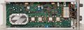
067-0587-02 left side (cam switch assembly on bottom left)
-
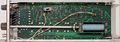
067-0587-02 right side (modified as 067-0587-10, note extra switch and resistor in top middle area of PCB)
-
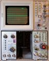
067-0587-02 in gain mode, vertical slot (horizontal lines)
-
067-0587-02 in gain mode, horizontal slot (vertical lines)
-
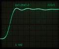
Rise time measurement of 7104 mainframe, 1000 Hz repetition rate. tr=240 ps (corrected for 150 ps fixture rise time = 190 ps equ. 1.8 GHz)
-
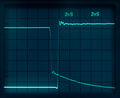
Rise and fall time of 067-0587-02 shown on separate timebases in 7104 (STEP RESP+)
-
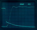
Rise and fall time of 067-0587-02 shown on separate timebases in 7104 (STEP RESP+), expanded scale


Components
Some Parts Used in the 067-0587-02
| Part | Part Number(s) | Class | Description | Used in |
|---|---|---|---|---|
| 155-0160-00 | 155-0160-00 | Monolithic integrated circuit | 1.5 GHz trigger amplifier and source select | 7B10 • 7B15 • 067-0587-02 • 067-0587-10 |
| 155-0175-00 | 155-0175-00 • 155-0175-05 | Monolithic integrated circuit | broadband amplifier | 7904A • 7912HB • 7934 • 7104 • R7103 • 7A29 • 7A29P • 7F10 • 067-0587-02 • 067-0587-10 • 11A71 • SCD1000 • EG&G N-AM-173A |
| 155-0182-00 | 155-0182-00 | Hybrid integrated circuit | Schottky diode shaper | 067-0587-02 • 067-0587-10 |
| 155-0183-00 | 155-0183-00 | Hybrid integrated circuit | Schottky diode detector | 067-0587-02 • 067-0587-10 |