109: Difference between revisions
(image, specs) |
No edit summary |
||
| (11 intermediate revisions by 2 users not shown) | |||
| Line 1: | Line 1: | ||
{{Instrument Sidebar | |||
|manufacturer=Tektronix | |||
|model=109 | |||
|class=Pulse generator | |||
|series= | |||
|summary=pulse generator | |||
|image=109 front crop.jpg | |||
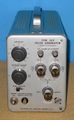
|caption=Tek 109 front | |||
|introduced=1962 | |||
|discontinued=(?) | |||
|designers= | |||
|manuals= | |||
* [[Media:070-299.pdf|Tektronix 109 Manual]] (PDF) | |||
* [[Media:062-0105-00.pdf|017-0067-00 Charging Network Datasheet]] | |||
}} | |||
The '''Tektronix Type 109''' is a pulse generator [[introduced in 1962]]. | The '''Tektronix Type 109''' is a pulse generator [[introduced in 1962]]. | ||
It uses a [[ | |||
and has a specified rise time of 250 ps. | It uses a [[GR-874]] 50 Ω output connector and has a specified rise time of 250 ps. | ||
{{BeginSpecs}} | {{BeginSpecs}} | ||
| Line 8: | Line 22: | ||
{{Spec | Pulse frequency | 550 to 720 Hz }} | {{Spec | Pulse frequency | 550 to 720 Hz }} | ||
{{Spec | Pulse length | 0.5 ns to 100 ns with a single charge line between the two charge line connectors, or up to 300 ns at half pulse rate with one open-ended charge line (other connector grounded)}} | {{Spec | Pulse length | 0.5 ns to 100 ns with a single charge line between the two charge line connectors, or up to 300 ns at half pulse rate with one open-ended charge line (other connector grounded)}} | ||
{{Spec | Pulse amplitude | Internal supply: 0 to 50 V variable in three ranges (0.5 V, 5 V, 50 V), positive or negative, or external up to | {{Spec | Pulse amplitude | Internal supply: 0 to 50 V variable in three ranges (0.5 V, 5 V, 50 V), positive or negative, or external up to ±300 V}} | ||
{{EndSpecs}} | {{EndSpecs}} | ||
==Internals== | |||
[[File:Charge line animation.gif|250px|right]] | [[File:Charge line animation.gif|250px|right]] | ||
The 109's operating principle is that of a | The 109's operating principle is that of a [http://en.wikipedia.org/wiki/Pulse_forming_network#Transmission_line_PFNs charged transmission line pulse generator] with a mechanical reed switch and external 50 Ω transmission line/lines attached through two GR-874 50 Ω connectors. | ||
[http://en.wikipedia.org/wiki/Pulse_forming_network#Transmission_line_PFNs charged transmission line pulse generator] | The length of the external cables determines the impulse width. | ||
with a mechanical reed switch and external | Using two transmission lines of non-equal length, alternating pulses having different width can be produced. | ||
The length of the external cables determines the impulse width. | Alternatively, an R-C network can be used to create pulses with R-C decay characteristic but longer duration. | ||
The pulse-generating switch in the 109 is a mechanical [[mercury switch]], which limits pulse frequency to about 600 Hz. | The pulse-generating switch in the 109 is a mechanical [[mercury switch]], which limits pulse frequency to about 600 Hz. | ||
Moreover, this switch has a relatively short life time (200 hours) | Moreover, this switch has a relatively short life time (200 hours) — if the operator forgets to shut the 109 down over the weekend and some holidays, the reed switch will need replacement. | ||
some holidays, the reed switch will need replacement. | |||
The internal voltage source is adjustable from 0 to 50 V in three ranges (0.5 V, 5 V, 50 V), either positive or negative. | The internal voltage source is adjustable from 0 to 50 V in three ranges (0.5 V, 5 V, 50 V), either positive or negative. | ||
Using | Using external voltage sources, pulses up to 300 V of either polarity are possible, including alternating positive/negative pulses. | ||
==Repair issues== | ==Repair issues== | ||
| Line 28: | Line 42: | ||
Be aware during servicing that the thermal breaker is on full mains and has no protection cover! | Be aware during servicing that the thermal breaker is on full mains and has no protection cover! | ||
== | ==Links== | ||
* [http:// | * [http://cds.linear.com/docs/en/application-note/an120f.pdf Jim Williams, Linear Technology Application Note 120, "1 ppm Settling Time Measurement for a Monolithic 18-Bit DAC"] - see Appendix H (p.30) | ||
* [ | * [https://w140.com/slac-tn-71-027.pdf Report comparing RG-58 with RG-174 using Tek 109 and Tek 661 (PDF)] | ||
* [https://www.amplifier.cd/Test_Equipment/Tektronix/Tektronix_other/109.html Tek 109 page @ amplifier.cd] | |||
==Pictures== | ==Pictures== | ||
<gallery> | <gallery> | ||
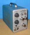
109_front.jpg | Front view | |||
109_right.jpg | Right internal | |||
109_left.jpg | Left internal | |||
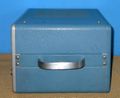
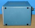
109_back.jpg | Rear view (connector not original) | |||
109_impulse.jpg | flying spot caught with 7904, S6, 7T11, 7M11. 2.5 V<sub>pk</sub>, T<sub>r</sub>=240 ps | |||
Tek 109 schematic.png | schematic | |||
Tek-017-067.jpg | [[017-067]] Charge network for 109 | |||
017-067.jpg | 017-067 Charge network for 109 (description) | |||
Tek 109 front.jpg | |||
Tek 109 front2.jpg | |||
Tek 109 top.jpg|top | |||
Tek 109 bottom.jpg|bottom | |||
</gallery> | </gallery> | ||
| Line 46: | Line 67: | ||
[[Category:Pulse generators]] | [[Category:Pulse generators]] | ||
[[Category:introduced in 1962]] | [[Category:introduced in 1962]] | ||
[[Category:GR874]] | |||
Latest revision as of 10:08, 18 August 2021

The Tektronix Type 109 is a pulse generator introduced in 1962.
It uses a GR-874 50 Ω output connector and has a specified rise time of 250 ps.
Key Specifications
| Rise time | 250 ps |
|---|---|
| Pulse frequency | 550 to 720 Hz |
| Pulse length | 0.5 ns to 100 ns with a single charge line between the two charge line connectors, or up to 300 ns at half pulse rate with one open-ended charge line (other connector grounded) |
| Pulse amplitude | Internal supply: 0 to 50 V variable in three ranges (0.5 V, 5 V, 50 V), positive or negative, or external up to ±300 V |
Internals

The 109's operating principle is that of a charged transmission line pulse generator with a mechanical reed switch and external 50 Ω transmission line/lines attached through two GR-874 50 Ω connectors. The length of the external cables determines the impulse width. Using two transmission lines of non-equal length, alternating pulses having different width can be produced. Alternatively, an R-C network can be used to create pulses with R-C decay characteristic but longer duration.
The pulse-generating switch in the 109 is a mechanical mercury switch, which limits pulse frequency to about 600 Hz. Moreover, this switch has a relatively short life time (200 hours) — if the operator forgets to shut the 109 down over the weekend and some holidays, the reed switch will need replacement.
The internal voltage source is adjustable from 0 to 50 V in three ranges (0.5 V, 5 V, 50 V), either positive or negative. Using external voltage sources, pulses up to 300 V of either polarity are possible, including alternating positive/negative pulses.
Repair issues
Be aware during servicing that the thermal breaker is on full mains and has no protection cover!
Links
- Jim Williams, Linear Technology Application Note 120, "1 ppm Settling Time Measurement for a Monolithic 18-Bit DAC" - see Appendix H (p.30)
- Report comparing RG-58 with RG-174 using Tek 109 and Tek 661 (PDF)
- Tek 109 page @ amplifier.cd
Pictures
-
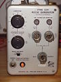
Front view
-
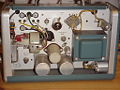
Right internal
-
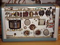
Left internal
-
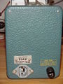
Rear view (connector not original)
-
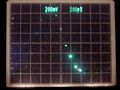
flying spot caught with 7904, S6, 7T11, 7M11. 2.5 Vpk, Tr=240 ps
-
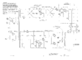
schematic
-
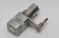
017-067 Charge network for 109
-
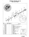
017-067 Charge network for 109 (description)
-
-
-
top
-
bottom


