11000 Series plug-in interface: Difference between revisions
No edit summary |
No edit summary |
||
| Line 20: | Line 20: | ||
The 11000-series interface uses pin B20 as an "11k Detector". | The 11000-series interface uses pin B20 as an "11k Detector". | ||
11000-series plug-ins have a pull-up resistor on pin B20. | 11000-series plug-ins have a pull-up resistor on pin B20. | ||
7000-series plug-ins left pin B20 unconnected. | 7000-series (vertical) plug-ins left pin B20 unconnected. | ||
<gallery> | <gallery> | ||
Revision as of 08:04, 11 April 2018
The Tektronix 11000 Series plug-in interface is mechanically almost identical to the 7000 Series plug-in interface. The only mechanical difference is that it at the top of the connector. The 11000 Series has a had a protruding narrow horn where the 7000 Series plug-ins have a wider horn at the top of the connector with electrical connections in some cases, e.g., in the 7A21.
The Tektronix 11000 Series plug-in interface is electrically partially the same as the 7000 Series interface. The power pins are the same, and the signal out pins are the same. 7000-series plug-ins provide a single trigger feed to the mainframe on pins A13/B13 (differential). 11000-series plug-ins also provide a trigger feed on pins A13/B13, and also provide trigger signals on B37/B38 and B35/B36.
11000-series plug-ins do not implement the 7000-series readout interface. The pins that are used for readout in the 7000-series are not used in the 11000 Series.
In the 11000 Series architecture, the mainframe communicates with the plug-in over a serial digital link called SDI. SDI uses pins A20, A21, and B21 on the plug-in connector. Those pins were not used on vertical plugins in the 7000-series interface (and the 11000-series does not support horizontal plugins).
11000-series mainframes send a calibration voltage to plug-in via pins B35/B36. Those pins were not used in the 7000-series interface.
The 11000-series interface uses pin B20 as an "11k Detector". 11000-series plug-ins have a pull-up resistor on pin B20. 7000-series (vertical) plug-ins left pin B20 unconnected.
-
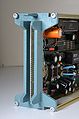
11000 Series connector
-
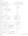
11000 Series pinout
-
7000 Series connector, for comparison


Pinout
| A side | B side | |
|---|---|---|
| Pin | Function | Function |
| 1 | Sweep Gate | n.c. |
| 2 | Gate common | n.c. |
| 3 | n.c. | n.c. |
| 4 | n.c. | n.c. |
| 5 | Sequence clock | n.c. |
| 6 | Ground | Sequence Sync |
| 7 | n.c. | n.c. |
| 8 | +5 V | n.c. |
| 9 | +5.1 V | n.c. |
| 10 | +5.1 V | Ground |
| 11 | +Vertical | −Vertical |
| 12 | Signal Ground | Signal Ground |
| 13 | +Trigger | −Trigger |
| 14 | Ground | +5.1 V |
| 15 | n.c. | n.c. |
| 16 | n.c. | n.c. |
| 17 | n.c. | Ground |
| 18 | +15 V | -15 V |
| 19 | n.c. | n.c. |
| 20 | SDI data MF→PI | 11k detector |
| 21 | SDI clock | SDI data PI→MF |
| 22 | Shield | Ground |
| 23 | n.c. | n.c. |
| 24 | n.c. | n.c. |
| 25 | n.c. | n.c. |
| 26 | n.c. | n.c. |
| 27 | n.c. | n.c. |
| 28 | n.c. | n.c. |
| 29 | -5 V | n.c. |
| 30 | -5 V | n.c. |
| 31 | n.c. | Ground |
| 32 | n.c. | Ground |
| 33 | Ground | n.c. |
| 34 | Ground | n.c. |
| 35 | −CH2 Trig out | Cal GND sense |
| 36 | +CH2 Trig out | Cal voltage |
| 37 | Ground | −CH1 Trig out |
| 38 | Ground | +CH1 Trig out |
Pin group function legend
Plugin power HF signals Plugin control interface