130: Difference between revisions
No edit summary |
m (Pics) |
||
| Line 40: | Line 40: | ||
Martin 130 10.jpg | Martin 130 10.jpg | ||
Martin 130 11.jpg | Martin 130 11.jpg | ||
Tek_Type130_Front.jpg | Type 130 Front | |||
Tek_Type130_Back.jpg | Type 130 Rear | |||
Tek_Type130_Top.jpg | Type 130 Top w/o Cover | |||
Tek_Type130_Bottom.jpg | Type 130 Bottom | |||
Tek_Type130_Inside-R.jpg | Type 130 Internal RHS | |||
Tek_Type130_Inside-L.jpg | Type 130 Internal LHS | |||
Tek_Type130_Inside-1.jpg | Type 130 Internal #1 | |||
Tek_Type130_Inside-2.jpg | Type 130 Internal #1 | |||
</gallery> | </gallery> | ||
[[Category:LCR meters]] | [[Category:LCR meters]] | ||
[[Category:Introduced in 1959]] | [[Category:Introduced in 1959]] | ||
Revision as of 21:52, 6 April 2019

The Tektronix Type 130 is a self-contained instrument that measures inductance and capacitance. The 130 makes an LC oscillator using the device under test and a capacitor or inductor internal to the 130. That oscillator's frequency is measured by mixing it down using a fixed reference frequency, generating a pulse at each zero-crossing, and integrating (low-pass filtering) the pulse train. This produces a voltage that is proportional to the frequency difference between the LC oscillator and the reference oscillator. This voltage is displayed on a d'Arsonval (moving coil) meter on the front panel of the 130.
The Type 130 was designed by Cliff Moulton.
Key Specifications
| Ranges | 3, 10, 30, 100 or 300 pF / 3, 10, 30, 100 or 300 μH full scale |
|---|---|
| Accuracy | 3% FS, 1% FS with "careful" calibration using S-30 Delta Standard |
| Measurement voltage | <1 V for capacitors, <0.25 V for inductors, 120-140 kHz |
| Guard output | 250 Ω source impedance, can drive 200 pF |
| DUT connection | UHF connector (DUT) + 4 mm jack (guard) |
Manuals
Links
- Q+A: Type 130 L-C Meter and S-30 Delta Standards. Service Scope No. 18, Feb 1963.
Pictures
-
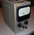
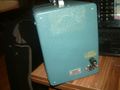
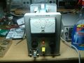
Early (Brown Era) Type 130
-
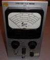
Early (Brown Era) Type 130
-
-
-
-
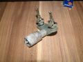
013-0001-00 test adapter
-
-
-
-
-
-
-
-
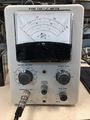
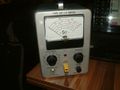
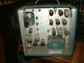
Type 130 Front
-
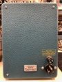
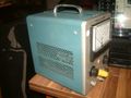
Type 130 Rear
-
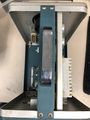
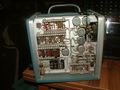
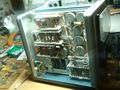
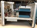
Type 130 Top w/o Cover
-
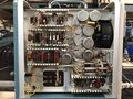
Type 130 Bottom
-

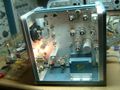
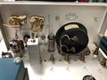
Type 130 Internal RHS
-
Type 130 Internal LHS
-
Type 130 Internal #1
-
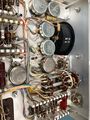
Type 130 Internal #1


