1401: Difference between revisions
m (test pdf link) |
m (log amp) |
||
| Line 9: | Line 9: | ||
catalog specify the resolution bandwidth selector as 1000, 100 and 3 KHz, | catalog specify the resolution bandwidth selector as 1000, 100 and 3 KHz, | ||
but the later versions are 100, 100, and 10 KHz. There is also a 1401A-1 | but the later versions are 100, 100, and 10 KHz. There is also a 1401A-1 | ||
which has a 75 ohm input impedance. | which has a 75 ohm input impedance. The predecessor 1401 did not have | ||
the calibrator out or pushbutton switch. | |||
The 1401A is designed to be used with an oscilloscope with 10 horizontal | The 1401A is designed to be used with an oscilloscope with 10 horizontal | ||
| Line 46: | Line 47: | ||
Image:tek1401a-bottom.jpg|Bottom PCBs:gate/cal, power supply | Image:tek1401a-bottom.jpg|Bottom PCBs:gate/cal, power supply | ||
Image:tek1401a-batterypcb.jpg|PCB on the battery pack | Image:tek1401a-batterypcb.jpg|PCB on the battery pack | ||
Image:Tek1401a-logamp.jpg|Cartoon in schematic diagram. Log Amp. | |||
</gallery> | </gallery> | ||
Revision as of 00:25, 12 October 2014

The Tektronix 1401A is a swept front-end spectrum analyzer covering the frequency range of 1 MHz to 500 MHz. It is designed to use an external oscilloscope, typically a 323, 324 or 326. It has internal rechargable NiCd batteries and can also operate from AC power (using an unusual power cord) or external DC from 6V to 16V.
There appear to be two variants of the 1401A, both the manual and catalog specify the resolution bandwidth selector as 1000, 100 and 3 KHz, but the later versions are 100, 100, and 10 KHz. There is also a 1401A-1 which has a 75 ohm input impedance. The predecessor 1401 did not have the calibrator out or pushbutton switch.
The 1401A is designed to be used with an oscilloscope with 10 horizontal divisions and 6 vertical divisions. Note that most full sized Tektronix oscilloscopes have 8 vertical divisions so use care when doing the initial setup and reading the scale in dBm.
See TekScope January 1972 pages 14-15 for some servicing notes that Tek wrote after the manual was published. Service Note
There is one tunnel diode found in the external trigger circuit. It is a 152-0402-00, a 2mA, 25pF tunnel diode in a DO-17 package. It's only necessary if you use the external trigger input.
There is one Tektronix custom IC, 155-0042-02, listed as a Miller Integrator. It is used to generate the sweep ramp voltage. The package is a 10 pin metal can.
The input attenuator is a fairly custom part due to the IF gain pot that is concentric with the RF atten control. Dissassembly of the attenuator is easy after removing it from the 1401A. Note that the IF gain pot is removed via two allen setscrews. To bench test the attenuator with DC, use a 50 ohm terminator on SMA input and connect the output SMA to an ohm meter. Each of the seven steps should read around 50 ohms. The contacts on the ceramic attenuator elements can wear, they can be repaired with silver solder. Before reassembly, remove the two SMA housings to avoid damaging the contacts and remove the setscrews that hold spring tension on the two ball bearings that align the shaft steps. Reinstall these parts after the housing has been screwed together.
-
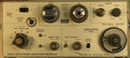
Front panel
-
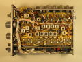
Top PCB: IF board
-
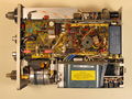
Bottom PCBs:gate/cal, power supply
-
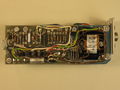
PCB on the battery pack
-
Cartoon in schematic diagram. Log Amp.


