1502: Difference between revisions
No edit summary |
No edit summary |
||
| (10 intermediate revisions by 2 users not shown) | |||
| Line 7: | Line 7: | ||
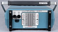
|image=Tek1502-front.JPG | |image=Tek1502-front.JPG | ||
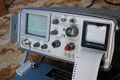
|caption=Tektronix 1502 Time Domain Reflectometer (CRT version) | |caption=Tektronix 1502 Time Domain Reflectometer (CRT version) | ||
|introduced= | |introduced=1975 | ||
|discontinued=(?) | |discontinued=(?) | ||
|designers=Hans Geerling | |designers=Hans Geerling | ||
|manuals= | |manuals= | ||
'''1502''' | '''1502''' | ||
* [ | * [[Media:070-1790-00.pdf|Tektronix 1502 Operators Manual]] | ||
* [[Media: | * [[Media:070-1792-01.pdf|Tektronix 1502 Service Manual -01]] | ||
* [[Media:070-1792-02.pdf|Tektronix 1502 Service Manual -02]] | |||
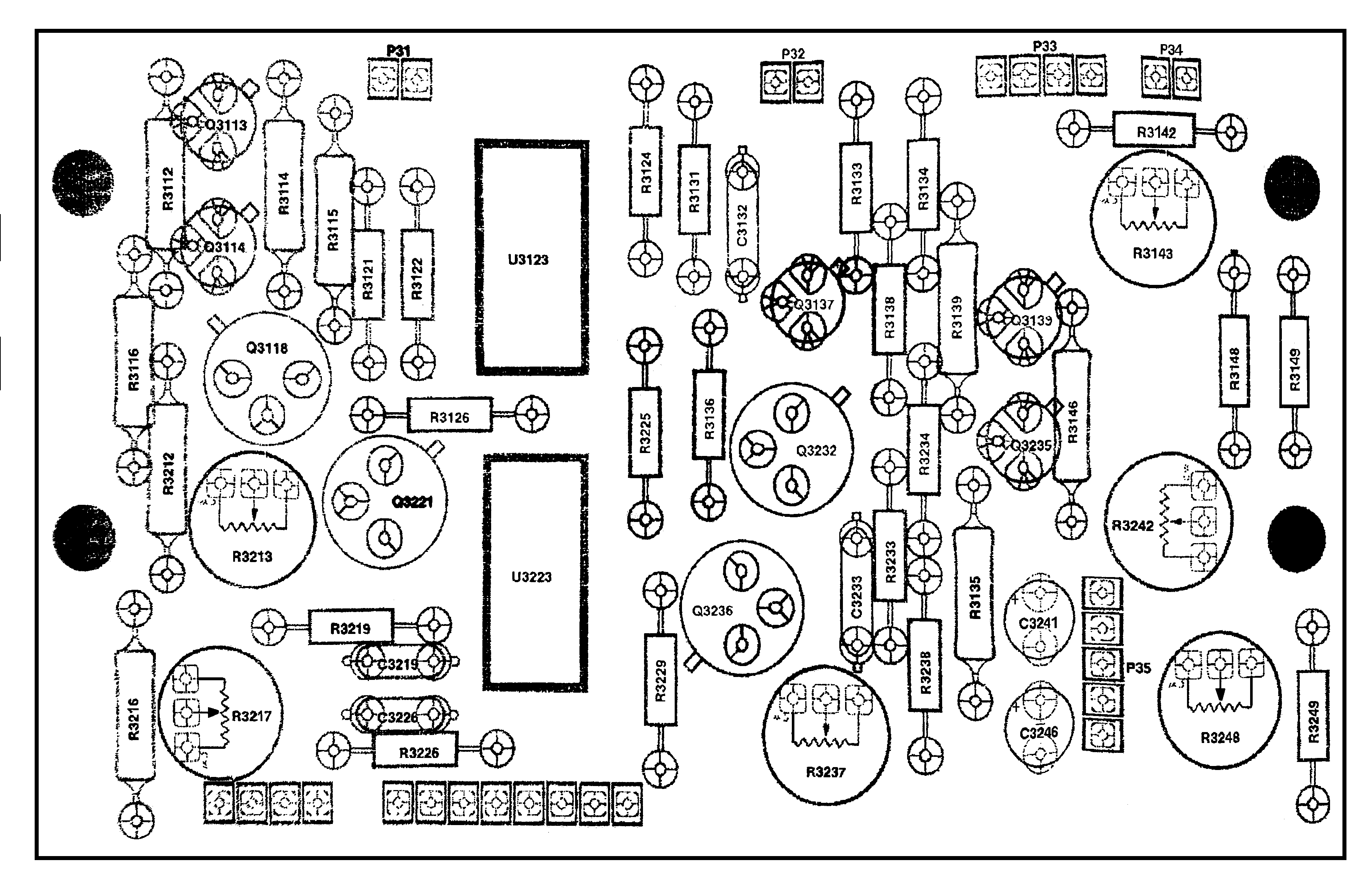
* High-res 1502 schematics: | |||
** [[Media:1502_Vertical_Amp.pdf|Vertical amp board]] | |||
** [[Media:1502_Schematic_Mainborad_Components.pdf|Main board]] | |||
** [[Media:1502_SCHEMATIC-Output_Amp.png|Output amplifier]] | |||
* [[Media:Tek_1502_Wizard_Workshop.pdf|Tektronix 1502 Wizard Workshop Articles]] | |||
* [[Media:Tek_1502_mods.pdf|Tektronix 1502 Modifications]] | |||
'''1502B''' | '''1502B''' | ||
* [ | * [[Media:070-6266-01.pdf|Tektronix 1502B Operator Manual]] | ||
* [[Media:070-6267-04.pdf|Tektronix 1502B Service Manual]] | |||
'''1502C''' | '''1502C''' | ||
* [ | * [[Media:070-7169-05.pdf|Tektronix 1502C User Manual]] | ||
* [[Media:070-7168-04.pdf|Tektronix 1502C Service Manual]] | |||
'''Other''' | '''Other''' | ||
* [[Media:Tektronix_Y-T_chart_recorder.pdf|Tektronix Chart Recorder User/Service Manual]] | * [[Media:Tektronix_Y-T_chart_recorder.pdf|Tektronix Chart Recorder User/Service Manual]] | ||
* [[Media:070-2178-00.pdf|Watertight Sealing Procedures for 1502/1503 TDRs]] | * [[Media:070-2178-00.pdf|Watertight Sealing Procedures for 1502/1503 TDRs]] | ||
* [[Media:Optimize falltime and aberrations 1502 | * [[Media:Optimize falltime and aberrations 1502.pdf|Guide to Optimizing Falltime and Aberrations in the 1502]] | ||
:''Note that the manuals for the 1502B and 1503C are still available from Tektronix.'' | :''Note that the manuals for the 1502B and 1503C are still available from Tektronix.'' | ||
}} | }} | ||
The '''Tektronix 1502''' is a series of Time Domain Reflectometers | The '''Tektronix 1502''' is a series of Time Domain Reflectometers which replaced the [[1501]] in 1975. The 1502 is for high resolution, sister model [[1503]] for long range. | ||
They are commonly used to test coaxial cables, although they have many other uses. | |||
The US military was a major purchaser, therefore most of the first series (the 1502, no letter) will be found surplus with some sort of US military property ID tag and an NSN sticker. | The US military was a major purchaser, therefore most of the first series (the 1502, no letter) will be found surplus with some sort of US military property ID tag and an NSN sticker. | ||
[[Hans Geerling]] did most of the circuit design on the 1502. | [[Hans Geerling]] did most of the circuit design on the 1502. | ||
{{MissingSpecs}} | |||
==Internals and version differences== | ==Internals and version differences== | ||
| Line 47: | Line 56: | ||
==Repair issues== | ==Repair issues== | ||
→ see [[1502/Repairs]] | |||
==Replacement== | |||
MOHR Test and Measurement manufactures a direct replacement to the 1502B and 1502C using an updated version of the same pulser/sampler. | |||
Any procedures or recorded waveforms are repeatable using the MOHR TDR.''[http://www.mohr-engineering.com/ct100 CT100B TDR Cable Analyzer]''. | |||
==Links== | |||
{{Documents|Link=1502}} | |||
==Prices== | |||
1979: $3,750 (~$14,700 in 2022 Dollars) | |||
According to an [[Media:Tek Schottky Diodes Memo rot.pdf|internal memo]], in 1979 annual sales were estimated at 543 units. | |||
==Pictures== | ==Pictures== | ||
'''1502''' | |||
<gallery> | <gallery> | ||
Tek1502-top.JPG|Top boards of the 1502 | Tek1502-top.JPG|Top boards of the 1502 | ||
| Line 96: | Line 82: | ||
TEK1502-HV-board-bottom.jpg|HV board bottom view | TEK1502-HV-board-bottom.jpg|HV board bottom view | ||
Tek 1502 with printer.jpg|Tek 1502 with printer | Tek 1502 with printer.jpg|Tek 1502 with printer | ||
Tek 1502 trace no connection.jpg | |||
1502_Front_metric_version.jpg|Tek 1502 Metric Version (Option 5) | |||
</gallery> | |||
'''1502B''' | |||
<gallery> | |||
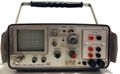
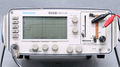
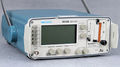
Tek 1502b 1.jpg|1502B | Tek 1502b 1.jpg|1502B | ||
Tek 1502b 2.jpg|1502B | Tek 1502b 2.jpg|1502B | ||
Tek 1502b 3.jpg|1502B | Tek 1502b 3.jpg|1502B | ||
Tek 1502b 4.jpg|1502B | Tek 1502b 4.jpg|1502B | ||
</gallery> | </gallery> | ||
[[Category:Time-domain reflectometers]] | [[Category:Time-domain reflectometers]] | ||
Latest revision as of 04:58, 11 March 2024

The Tektronix 1502 is a series of Time Domain Reflectometers which replaced the 1501 in 1975. The 1502 is for high resolution, sister model 1503 for long range.
They are commonly used to test coaxial cables, although they have many other uses. The US military was a major purchaser, therefore most of the first series (the 1502, no letter) will be found surplus with some sort of US military property ID tag and an NSN sticker.
Hans Geerling did most of the circuit design on the 1502.
Key Specifications
- please add
Internals and version differences
The first version used a CRT and is an almost completely analog design except for some discrete digital logic used to pre-fire and fire the tunnel diode pulser. The later models (1502B/C) used a liquid-crystal display and a Z80 microprocessor.
The other major difference between versions is the line charging method. The 1502 uses a fast (36 ps) tunnel diode pulser, the later models used a half sine wave to charge the line. The TD pulser, with its Dirac delta edge, gives much better short range sensitivity, although it is much easier to destroy.
Repair issues
→ see 1502/Repairs
Replacement
MOHR Test and Measurement manufactures a direct replacement to the 1502B and 1502C using an updated version of the same pulser/sampler. Any procedures or recorded waveforms are repeatable using the MOHR TDR.CT100B TDR Cable Analyzer.
Links
Documents Referencing 1502
| Document | Class | Title | Authors | Year | Links |
|---|---|---|---|---|---|
| Tekscope 1975 V7 N2.pdf | Article | Two Weatherproof TDR Cable Testers for Field Use | Ivan Ivanov | 1975 | 1502 • 1503 |
| Tekscope 1975 V7 N3.pdf | Article | New Products | 1975 | 5444 • 1502 • 1503 • 455 • E4010 • E4010-1 • 4923 • 2701 • 2703 • J6523 • WP1205 | |
| TekWeek (partial) October 10, 1975.pdf | Article | Spectrum analyzers require high technology | Thor Hallen • Dave Friedley | 1975 | Spectrum Analyzers • Pentrix • 7L5 • 5L4 • 7L12 • 7L13 • 1401 • 491 • 1405 • 1502 • 1503 |
Prices
1979: $3,750 (~$14,700 in 2022 Dollars)
According to an internal memo, in 1979 annual sales were estimated at 543 units.
Pictures
1502
-
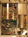
Top boards of the 1502
-
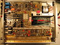
Underside of 1502 with stripline sampler and pulser exposed
-
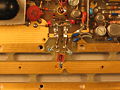
Sampling gate near the BNC end of stripline
-
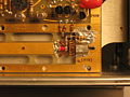
Pulser end of the stripline
-
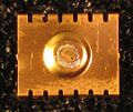
Pulser TD removed from stripline
-
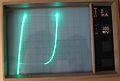
Pulser TD curve traced with a 576
-
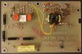
HV board top view
-
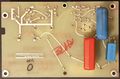
HV board bottom view
-
Tek 1502 with printer
-

-
Tek 1502 Metric Version (Option 5)


1502B
-
1502B
-
1502B
-
1502B
-
1502B


