1A1: Difference between revisions
No edit summary |
Vintage dave (talk | contribs) (specs and history) |
||
| Line 1: | Line 1: | ||
The Type 1A1 plug-in has two channels and a -3dB point of 50MHz. | The Type 1A1 plug-in has two channels and a -3dB point of 50MHz at 50mV/div, 28MHz at 5mV/div, | ||
the is sent by scopes on pin 7 of the plug-in connector. | and 2Hz to 15MHz at 500uV/div when channels 1 and 2 are cascaded. | ||
Early production used a Nuvistor front-end, and rotary input switches that were concentric | |||
with the BNC jacks, while later units have FETs and lever switches. The 1A1 uses the "ALT SWEEP SLAVE PULSE" signal | |||
the is sent by scopes on pin 7 of the plug-in connector. In a Type [[547]] mainframe, this signal allows channel 1 to be | |||
displayed using the "A" timebase and channel 2 is to be displayed using the "B" timebase. | displayed using the "A" timebase and channel 2 is to be displayed using the "B" timebase. | ||
This is useful, for example, to view the IF and AF of a radio receiver at the same time. | This is useful, for example, to view the IF and AF of a radio receiver at the same time. | ||
Types 1A1 and [[1A2]] were introduced together in 1964, the former for high-end use, | |||
the latter as an upgrade/replacement for Type [[CA]]. | |||
<gallery> | <gallery> | ||
Image:1a1_frontend.png|Early 1A1 front end | Image:1a1_frontend.png|Early 1A1 front end | ||
</gallery> | </gallery> | ||
Revision as of 19:23, 17 September 2010
The Type 1A1 plug-in has two channels and a -3dB point of 50MHz at 50mV/div, 28MHz at 5mV/div, and 2Hz to 15MHz at 500uV/div when channels 1 and 2 are cascaded. Early production used a Nuvistor front-end, and rotary input switches that were concentric with the BNC jacks, while later units have FETs and lever switches. The 1A1 uses the "ALT SWEEP SLAVE PULSE" signal the is sent by scopes on pin 7 of the plug-in connector. In a Type 547 mainframe, this signal allows channel 1 to be displayed using the "A" timebase and channel 2 is to be displayed using the "B" timebase. This is useful, for example, to view the IF and AF of a radio receiver at the same time.
Types 1A1 and 1A2 were introduced together in 1964, the former for high-end use, the latter as an upgrade/replacement for Type CA.
-
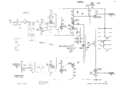
Early 1A1 front end
