1A5: Difference between revisions
No edit summary |
No edit summary |
||
| (23 intermediate revisions by 4 users not shown) | |||
| Line 1: | Line 1: | ||
{{Plugin Sidebar | {{Plugin Sidebar | ||
|manufacturer=Tektronix | |||
summary=50 MHz Differential Amplifier | | |type=1A5 | ||
image=1a5 | |summary=50 MHz Differential Amplifier | ||
caption=Tektronix 1A5 Differential Amplifier | | |image=Tek 1a5 front2.jpeg | ||
series= | |caption=Tektronix 1A5 Differential Amplifier | ||
introduced=1967 | | |series=500-series scopes | ||
discontinued=1975 | | |introduced=1967 | ||
manuals= | |discontinued=1975 | ||
* [ | |designers=Bill DeVey | ||
|manuals= | |||
* [[Media: | * [[Media:070-0638-00.pdf|Tektronix 1A5 Manual]] (OCR) | ||
* [[Media:Tek Type 1A5 FCP 1969.pdf|Tektronix Type 1A5 Factory Calibration Procedure, March 1969]] (OCR) | |||
* [[Media:Tek 1a5 fcp sep 1967.pdf|Tektronix 1A5 Factory Calibration Procedure, September 1967]] | |||
* [[Media:Tek 1a5 cal outline.pdf|Tektronix 1A5 Calibration Outline]] (OCR) | |||
}} | }} | ||
The '''Tektronix Type 1A5''' is a differential amplifier plug-in for [[500-series scopes]]. | The '''Tektronix Type 1A5''' is a differential amplifier plug-in for [[500-series scopes]]. | ||
It was designed by [[Bill DeVey]] after consultation with [[John Kobbe]]. | |||
It has an [[Amphenol 165 series connector]] on the front panel for direct connection of the Type [[P6046|P6046 Active Differential Probe]]. | It has an [[Amphenol 165 series connector]] on the front panel for direct connection of the Type [[P6046|P6046 Active Differential Probe]]. | ||
| Line 19: | Line 23: | ||
{{BeginSpecs}} | {{BeginSpecs}} | ||
{{Spec | Bandwidth | {{Spec | Bandwidth | 50 MHz down to 5 mV/div, 40 MHz at 1 mV/div }} | ||
{{Spec | Deflection | 1 mV/div to 20 V/div, 1−2−5 }} | {{Spec | Deflection | 1 mV/div to 20 V/div, 1−2−5 }} | ||
{{Spec | Common-mode rejection | 20,000:1 | {{Spec | Common-mode rejection | 20,000:1 from DC to 100 kHz, 10,000:1 up to 1 MHz, 200:1 at 20 MHz }} | ||
{{EndSpecs}} | {{EndSpecs}} | ||
| Line 29: | Line 33: | ||
V<sub>C</sub> is controlled by a ten-turn potentiometer and can vary from −5 V to +5 V (0.5 V on the 5 V/div to 20 V/div ranges). | V<sub>C</sub> is controlled by a ten-turn potentiometer and can vary from −5 V to +5 V (0.5 V on the 5 V/div to 20 V/div ranges). | ||
[[ | ==Internals== | ||
The 1A5 is solid-state except for a pair of [[7586|7586 nuvistors]] used in the upper half of a cascode in the second amplifier stage. | |||
The attenuator switching is mechanically complex. A gear mechanism drives the input attenuator switch (under the internal cover) selecting attenuators ×1000 (20 V/div to 5 V/div), ×100 (2 V/div to 500 mV/div), ×10 (200 mv/div to 50 mV/Div) or no attenuators (20 mV/Div to 1 mV/div). | |||
Additionally, in the 500 mV/div and 50 mV/div positions, the operator can pull the V/Div knob outward when switching to one of the next two more sensitive ranges, in which case the higher attenuator (and higher input and comparison voltage range) remains in place. | |||
==Pictures== | ==Pictures== | ||
<gallery> | <gallery> | ||
1a5 | Tek 1a5 front2.jpeg | ||
1a5 right2. | </gallery> | ||
1a5 right.jpg | |||
1a5 | '''Interior''' | ||
<gallery> | |||
Tek 1A5 left wo cover.jpg | Left side (attenuator cover removed) | |||
1A5 output board.jpg | Output board (left side) with HF Comp. daughterboard removed to show reed relays | |||
Tek 1A5 right.jpg | Right side | |||
Tek 1a5 left2.jpeg | Left side (attenuator cover in place) | |||
Tek 1a5 right2.jpeg | Right side | |||
Tek 1a5 top2.jpeg | Top | |||
1a5 right.jpg | Top | |||
Tek 1a5 bottom2.jpeg | Bottom | |||
Tek 1a5 rear2.jpeg | Rear | |||
</gallery> | |||
'''Switches detail''' | |||
<gallery> | |||
Tek 1A5 switches 1.jpg | |||
Tek 1A5 switches 2.jpg | |||
Tek 1A5 switches 3.jpg | |||
Tek 1A5 switches 4.jpg | |||
Tek 1A5 switches 5.jpg | |||
</gallery> | </gallery> | ||
==Components== | |||
{{Parts|1A5}} | |||
[[Category:500 series plugins]] | [[Category:500 series plugins]] | ||
[[Category:Differential amplifiers]] | |||
Latest revision as of 05:41, 12 February 2024

The Tektronix Type 1A5 is a differential amplifier plug-in for 500-series scopes. It was designed by Bill DeVey after consultation with John Kobbe.
It has an Amphenol 165 series connector on the front panel for direct connection of the Type P6046 Active Differential Probe.
Type 1A5 was introduced in 1967, replacing Types W and Z, and lasted until the end of the 500-series scope line.
Key Specifications
| Bandwidth | 50 MHz down to 5 mV/div, 40 MHz at 1 mV/div |
|---|---|
| Deflection | 1 mV/div to 20 V/div, 1−2−5 |
| Common-mode rejection | 20,000:1 from DC to 100 kHz, 10,000:1 up to 1 MHz, 200:1 at 20 MHz |
Like most Tektronix differential plug-ins, the 1A5 has three modes: VA−VC, VA−VB, and VC−VB.
VC is controlled by a ten-turn potentiometer and can vary from −5 V to +5 V (0.5 V on the 5 V/div to 20 V/div ranges).
Internals
The 1A5 is solid-state except for a pair of 7586 nuvistors used in the upper half of a cascode in the second amplifier stage.
The attenuator switching is mechanically complex. A gear mechanism drives the input attenuator switch (under the internal cover) selecting attenuators ×1000 (20 V/div to 5 V/div), ×100 (2 V/div to 500 mV/div), ×10 (200 mv/div to 50 mV/Div) or no attenuators (20 mV/Div to 1 mV/div).
Additionally, in the 500 mV/div and 50 mV/div positions, the operator can pull the V/Div knob outward when switching to one of the next two more sensitive ranges, in which case the higher attenuator (and higher input and comparison voltage range) remains in place.
Pictures
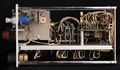
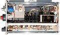
Interior
-

Left side (attenuator cover removed)
-
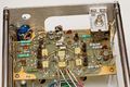
Output board (left side) with HF Comp. daughterboard removed to show reed relays
-
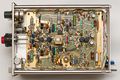
Right side
-
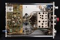
Left side (attenuator cover in place)
-
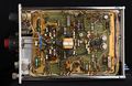
Right side
-
Top
-
Top
-

Bottom
-
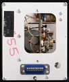
Rear


Switches detail


Components
Some Parts Used in the 1A5
| Part | Part Number(s) | Class | Description | Used in |
|---|---|---|---|---|
| 7586 | 154-0306-00 | Vacuum Tube (Triode) | Nuvistor triode | M • 1A1 • 1A2 • 1A5 • 10A2 • 10A2A • 11B1 • 11B2A • 321 • 321A • 3A1 • 3A1S • 3A3 • 3A5 • 3A6 • 3A7 • 3A8 • 3A74 • 3S76 • 3T77 • 3T77A • 3B5 • 4S1 • 4S2 • 6R1 • 6R1A • 9A1 • 9A2 • 82 • 86 • S-311 |