1S2: Difference between revisions
No edit summary |
No edit summary |
||
| (23 intermediate revisions by 4 users not shown) | |||
| Line 1: | Line 1: | ||
{{Plugin Sidebar | {{Plugin Sidebar | ||
|manufacturer=Tektronix | |||
summary=Sampling system/TDR| | |series=500-series scopes | ||
image= | |type=1S2 | ||
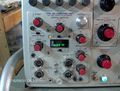
caption=1S2 front view| | |summary=Sampling system/TDR | ||
introduced=1967 | | |image=Tek 1s2 front.jpg | ||
discontinued=1973 | | |caption=1S2 front view | ||
|introduced=1967 | |||
manuals= | |discontinued=1973 | ||
* [ | |designers=Chuck Edgar;Gene Cowan | ||
* [ | |manuals= | ||
* [ | * [[Media:070-0889-00.pdf|1S2 manual]] (S/N 1990+, OCR) | ||
* ''Manual needed for sn below 1990 [[Category:Manual needed]]'' | |||
* [[Media:Tek 1s2 fcp june 1966.pdf|Tektronix 1S2 Factory Calibration Procedure, June 1966]] | |||
* [[Media:Tek 1s2 fcp aug 1968.pdf|Tektronix 1S2 Factory Calibration Procedure, August 1968]] | |||
* [[Media:Tek 1s2 cal outline.pdf|Tektronix 1S2 Calibration Outline]] | |||
<!-- * [[Media:1S2_calibration_guide.pdf|1S2 Calibration Guide by Fred Schneider, PA4TIM]] --> | |||
}} | }} | ||
The '''Tektronix 1S2''' is a [[sampling oscilloscope|sampling]]/TDR plug-in for [[500-series scopes]]. | The '''Tektronix 1S2''' is a [[sampling oscilloscope|sampling]]/TDR plug-in for [[500-series scopes]], [[introduced in 1967]] and sold through 1972. | ||
[[Chuck Edgar]] designed the sweep circuitry and [[Gene Cowan]] designed the vertical circuitry. | |||
Like the [[1S1]], it is a complete sampling subsystem and uses the mainframe merely as a power supply and low-speed X-Y display. | Like the [[1S1]], it is a complete sampling subsystem and uses the mainframe merely as a power supply and low-speed X-Y display. | ||
The 1S2 outputs the Y-axis signal on plug-in interface connector pins 1 and 3 like other 500-series plug-ins | The 1S2 outputs the Y-axis signal on plug-in interface connector pins 1 and 3 like other 500-series plug-ins, and the X-axis signal on the front panel, via a banana connector. The X-axis sensitivity of the oscilloscope mainframe is expected to be 1 V/div. | ||
The X-axis sensitivity of the oscilloscope mainframe is expected to be 1 V/div. | |||
Unlike the 1S1, | Unlike the 1S1, the 1S2 contains pulsers that allows it to perform time-domain reflectometry (TDR) measurements. | ||
The 1S2 has two 50 Ω pulsers, one of which is active at a time. One puts out a 250 mV pulse with 50 ps rise time. | The 1S2 has two 50 Ω pulsers, one of which is active at a time. One puts out a 250 mV pulse with 50 ps rise time. | ||
The other puts out a slower | The other puts out a slower 1 V pulse. The sampling bridge is a feed-through type. | ||
For TDR measurements, the signal from one of the internal pulsers is fed through the sampler, and out to | For TDR measurements, the signal from one of the internal pulsers is fed through the sampler, and out to the transmission line being tested. | ||
Returning pulses are detected as they pass back through the sampler, and they are reabsorbed by the 50 Ω impedance of the pulser. | Returning pulses are detected as they pass back through the sampler, and they are reabsorbed by the 50 Ω impedance of the pulser. | ||
Waveform output can be to the CRT of the mainframe and/or to a plotter or low-speed data acquisition device via banana connectors on the front of the 1S2. | Waveform output can be to the CRT of the mainframe and/or to a plotter or low-speed data acquisition device via banana connectors on the front of the 1S2. | ||
The 1S2 | The interface between the GR-874 connector and the printed circuit board is described in US Patent 3,426,311. | ||
{{MissingSpecs}} | |||
==Internals== | |||
The 1S2 contains an internal power supply producing regulated +19 V, -19 V, and -136 V outputs, | |||
derived from a power transformer whose primary voltage is the 6.3 V<sub>AC</sub> | |||
provided by the 500-series mainframe on pins 13 and 14 of the plug-in interface connector. | |||
The regulators use bipolar transistors for the feedback amplifiers and the output emitter-followers, and zener diodes as references. | |||
==Links== | ==Links== | ||
* [[Media:062-1244-00.pdf | Tektronix 062-1244-00: Time-Domain Reflectometry Measurement Concepts]], James A. Strickland, 1969. | * [https://www.pa4tim.nl/wp-content/uploads/2012/01/1S2calibrationPA4TIM.pdf 1S2 Calibration Guide by Fred Schneider, PA4TIM] | ||
* [https://www.pa4tim.nl/?p=3016 1S2 Page on the Website of Fred Schneider, PA4TIM] | |||
* [[Media:062-1244-00.pdf | Tektronix 062-1244-00: Time-Domain Reflectometry Measurement Concepts]], James A. Strickland, 1969. OCR, 6.2 MB | |||
* [[Media:Service Scope 45 Aug 1967.pdf | Service Scope No. 45, August 1967 - Time-Domain Reflectometry Theory]] | * [[Media:Service Scope 45 Aug 1967.pdf | Service Scope No. 45, August 1967 - Time-Domain Reflectometry Theory]] | ||
* [[Media:Service Scope 38 Jun 1966.pdf | Service Scope No. 38, June 1966 - Tektronix Type 1S2 Makes Reflectometry Easy]] | * [[Media:Service Scope 38 Jun 1966.pdf | Service Scope No. 38, June 1966 - Tektronix Type 1S2 Makes Reflectometry Easy]] | ||
* [ | * [https://www.picosecond.com/objects/AN-04.pdf Picosecond Pulse Labs Application Note 4: TDR] | ||
==Pictures== | ==Pictures== | ||
| Line 52: | Line 65: | ||
Tek 1s2 e 6.jpg | Tek 1s2 e 6.jpg | ||
Tek 1s2 e 7.jpg | Tek 1s2 e 7.jpg | ||
Tek 1s2 regulated ps.png|Internal Regulated Power Supply | |||
Tek 1s2 rear.jpg|rear | |||
</gallery> | </gallery> | ||
| Line 59: | Line 74: | ||
[[Category:Time-domain reflectometers]] | [[Category:Time-domain reflectometers]] | ||
[[Category:500 series plugins]] | [[Category:500 series plugins]] | ||
[[Category:GR874]] | |||
[[Category:Manual needed]] | |||
Latest revision as of 03:04, 11 September 2023

The Tektronix 1S2 is a sampling/TDR plug-in for 500-series scopes, introduced in 1967 and sold through 1972. Chuck Edgar designed the sweep circuitry and Gene Cowan designed the vertical circuitry.
Like the 1S1, it is a complete sampling subsystem and uses the mainframe merely as a power supply and low-speed X-Y display. The 1S2 outputs the Y-axis signal on plug-in interface connector pins 1 and 3 like other 500-series plug-ins, and the X-axis signal on the front panel, via a banana connector. The X-axis sensitivity of the oscilloscope mainframe is expected to be 1 V/div.
Unlike the 1S1, the 1S2 contains pulsers that allows it to perform time-domain reflectometry (TDR) measurements. The 1S2 has two 50 Ω pulsers, one of which is active at a time. One puts out a 250 mV pulse with 50 ps rise time. The other puts out a slower 1 V pulse. The sampling bridge is a feed-through type.
For TDR measurements, the signal from one of the internal pulsers is fed through the sampler, and out to the transmission line being tested. Returning pulses are detected as they pass back through the sampler, and they are reabsorbed by the 50 Ω impedance of the pulser.
Waveform output can be to the CRT of the mainframe and/or to a plotter or low-speed data acquisition device via banana connectors on the front of the 1S2.
The interface between the GR-874 connector and the printed circuit board is described in US Patent 3,426,311.
Key Specifications
- please add
Internals
The 1S2 contains an internal power supply producing regulated +19 V, -19 V, and -136 V outputs, derived from a power transformer whose primary voltage is the 6.3 VAC provided by the 500-series mainframe on pins 13 and 14 of the plug-in interface connector. The regulators use bipolar transistors for the feedback amplifiers and the output emitter-followers, and zener diodes as references.
Links
- 1S2 Calibration Guide by Fred Schneider, PA4TIM
- 1S2 Page on the Website of Fred Schneider, PA4TIM
- Tektronix 062-1244-00: Time-Domain Reflectometry Measurement Concepts, James A. Strickland, 1969. OCR, 6.2 MB
- Service Scope No. 45, August 1967 - Time-Domain Reflectometry Theory
- Service Scope No. 38, June 1966 - Tektronix Type 1S2 Makes Reflectometry Easy
- Picosecond Pulse Labs Application Note 4: TDR
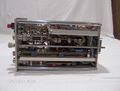
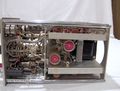
Pictures
-
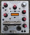
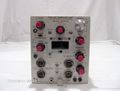
front view
-
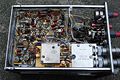
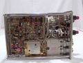
left side view
-
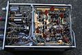
right side view
-
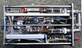
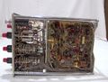
bottom view
-
time mode
-

distance mode
-
-
-
-
-
-
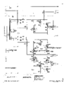
Internal Regulated Power Supply
-
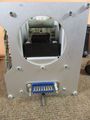
rear


