310: Difference between revisions
No edit summary |
No edit summary |
||
| (27 intermediate revisions by 3 users not shown) | |||
| Line 1: | Line 1: | ||
{{Oscilloscope Sidebar| | {{Oscilloscope Sidebar | ||
|manufacturer=Tektronix | |||
image= | |series=300-series scopes | ||
caption=Tektronix | |model=310A | ||
introduced=1955 | | |summary=4 MHz oscilloscope | ||
discontinued=1972 | | |image=Tek_310A_front.jpg | ||
|caption=Tektronix 310A,front view | |||
manuals= | |introduced=1955 | ||
* [ | |discontinued=1972 | ||
* [ | |designers=Frank Hood;John Kobbe | ||
* [ | |manuals= | ||
'''310''' | |||
* [ | * [[Media:IM-310-2.pdf|Tektronix 310 Manual IM-310-2 (early)]] | ||
* [ | * [[Media:070-244.pdf|Tektronix 310/310A Manual 070-244]] | ||
* | * [[Media:070-0892-00.pdf|Tektronix 310 Manual 070-0892-00]] (rough, bad-OCR) | ||
* [[Media:Tek_310_ad_Electronics_May_1955.pdf|Tek 310 ad in Electronics, May 1955]] | |||
'''310A''' | |||
* [[Media:070-0893-00.pdf|Tektronix 310A Manual]] (OCR)<br /><small>Alternate: [https://w140.com/tek_310a.djvu DjVu] / [https://bama.edebris.com/manuals/tek/310a/ Tek 310A manuals @ BAMA]</small> | |||
<small> | |||
===Calibration Procedures=== | |||
* [[Media:tek_310_fcp.pdf|Tektronix 310 Factory Calibration Procedure]] (bad-OCR) | |||
* [[Media:tek_310a_fcp.pdf|Tektronix 310A Factory Calibration Procedure]] (bad-OCR) | |||
* [[Media:Tek 310a fcp oct 1968 with 1969 updates.pdf|Tektronix 310A Factory Calibration Procedure with 1969 updates]] | |||
* [[Media:Tek 310a cal outline.pdf|Tektronix 310A Calibration Outline]] (OCR) | |||
</small> | |||
<small> | |||
===Modifications=== | |||
* [[Media:Tek 310a mod 109a.pdf|Tektronix 310A Mod 109A, High-Altitude Modification]] | |||
* [[Media:Tek 310a mod 812s.pdf|Tektronix 310A Mod 812S, Vertical Input Connector Changed to UHF]] | |||
* [[Media:Tek 310a mod 222a.pdf|Boeing Black-out]] | |||
* [[Media:Tek 310a mod 815e.pdf|Tektronix 310A Mod 812S, Trigger and Calibrator Connectors Changed to BNC]] | |||
* [[Media:Tek 310a mod 812z.pdf|Tektronix 310A Mod 812S, Input, Trigger, and Calibrator Connectors Changed to UHF]] | |||
* [[Media:Tek 310 silicon rectifier mod.pdf|Tektronix 310 Silicon Rectifier Mod]] | |||
* [[Media:Tek 310a mod 119F.pdf|Tektronix 310A Mod 119F]] | |||
* [[Media:Tek 310a mod 120H.pdf|Tektronix 310A Mod 120H]] | |||
</small> | |||
}} | |||
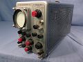
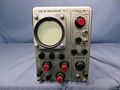
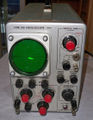
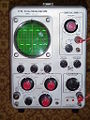
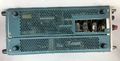
The '''Tektronix 310''' is a compact portable oscilloscope, designed by [[Frank Hood]] and [[John Kobbe]], that was [[introduced in 1955]]. | |||
It is a 4 MHz single-trace, single-timebase scope with a 3" (7.5 cm) round CRT. | |||
A revised version, the '''310A''', was [[introduced in 1959]]. | |||
While the 310 used printed-circuit boards, the 310A returned to ceramic strip construction in the interest of reliability. <small>''Is this the only time that a Tek design was moved from PCB back to ceramic strip?''</small> | |||
The [[Hickok]] company produced a clone of the | The [[Hickok]] company produced a clone of the 310A under a US military contract as the [[Hickok AN/USM89B|AN/USM89B]]. | ||
{{BeginSpecs}} | {{BeginSpecs}} | ||
{{Spec | Bandwidth | 4 MHz (3.5 MHz below 0.1 V/Div, AC coupled) }} | {{Spec | Bandwidth | 4 MHz (3.5 MHz below 0.1 V/Div, AC coupled) }} | ||
{{Spec | Rise time | 90 ns (100 ns below 0.1 V/Div, AC coupled) }} | {{Spec | Rise time | 90 ns (100 ns below 0.1 V/Div, AC coupled) }} | ||
{{Spec | | {{Spec | Sweep | 0.5 μs/Div to 0.2 s/Div 1–2–5 }} | ||
{{Spec | Deflection | 10 mV/Div to 50 V/Div, | {{Spec | Deflection | 10 mV/Div to 50 V/Div, 1–2–5 (below 0.1 V/Div only AC coupled) }} | ||
{{Spec | Input impedance | 1 MΩ // 40 pF }} | {{Spec | Input impedance | 1 MΩ // 40 pF }} | ||
{{Spec | X input | 1.5 V/Div, 500 kHz, 100 kΩ }} | {{Spec | X input | 1.5 V/Div (variable down), 500 kHz, 100 kΩ }} | ||
{{Spec | Z input | 20 V<sub>p-p</sub> at rear "CRT Cathode" binding post }} | {{Spec | Z input | 20 V<sub>p-p</sub> at rear "CRT Cathode" binding post }} | ||
{{Spec | Calibrator | | {{Spec | Calibrator | 50 mV<sub>p-p</sub> to 100 V<sub>p-p</sub>, 1–2–5; 1 kHz }} | ||
{{Spec | Power | 175 W }} | {{Spec | Power | 175 W }} | ||
{{EndSpecs}} | {{EndSpecs}} | ||
P2 [[phosphor]] was standard. P1, P7 and P11 were also available. | |||
==Links== | |||
* [https://richardsears.wordpress.com/2011/11/18/tektronix-310a/ Richard Sears: Tektronix 310 and 310A] | |||
* A Tek 310 restoration @ YouTube: [https://www.youtube.com/watch?v=Ef-6Vfx1oiY Part 1] / [https://www.youtube.com/watch?v=6HG49aX_TlM Part 2] | |||
{{Documents|Link=310}} | |||
{{Documents|Link=310A}} | |||
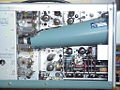
==Internals== | ==Internals== | ||
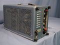
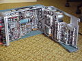
The scope cabinet was hinged to allow it to be opened like a book and operated for access to the circuitry for service purposes. | |||
The | |||
===Cooling=== | |||
The 310 is a tube scope and consumes 175 watts, but it does not have a fan. | |||
== | It therefore tends to run hot, particularly when used in a hot environment with still air. | ||
It has a 74 °C (165 °F) [[thermal cutoff]] switch in series with the primary of the power transformer. | |||
For extended use in one place, a tilted fan base, the [[FB310]] (part number 016-012) was available. | |||
The fan base blows air upward through the perforated bottom panel of the 310. | |||
While the scope had universal primary wiring options, the fan base did not. Separate models were available for 115 V<sub>AC</sub> or 230 V<sub>AC</sub> operation. | |||
The scope has feet on the rear panel to allow it to be operated on the floor with the front panel facing up, but the manual warns against prolonged operation in this orientation. | |||
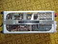
===Components=== | |||
and | The 310 is a nearly true pure vacuum-tube scope, but in the power supply there are some silicon rectifiers, and there is one germanium point contact diode in the circuit. | ||
Early examples of the Tektronix Type 310A used commodity 3WPx CRTs. At some point in production, | Early examples of the Tektronix Type 310A used commodity 3WPx CRTs. | ||
they switched to | At some point in production, they switched to the Tek-made [[T3100]] CRT, which is compatible with the [[3WP2]]. | ||
Unlike later Tek instruments, where the incremental model designated by an “A” suffix only occurred with a significant specification or performance enhancement, the original 310 and 310A were essentially identical. They even shared the same manual and schematics. The main difference was the wiring construction. | ===310A changes=== | ||
Unlike later Tek instruments, where the incremental model designated by an “A” suffix only occurred with a significant specification or performance enhancement, the original 310 and 310A were essentially identical. | |||
They even shared the same manual and schematics. The main difference was the wiring construction. <small>''needs to be checked - different tubes used according to the manuals'' </small> | |||
The original 310 pioneered the use of circuit board construction, rather than the trusted ceramic strip point to point wiring. The circuit boards were two sided, however | The original 310 pioneered the use of circuit board construction, rather than the trusted ceramic strip point to point wiring. | ||
which was expanded in a press before the components were installed in the board. The rivets themselves were not soldered to the copper foil traces, and relied on the pressure from the crimp to make contact. This proved to be extremely unreliable, with many intermittent connections resulting in high warranty- and after-warranty failure. | The circuit boards were two-sided, however, Tektronix did not use through-hole plating although this had been introduced in 1947<ref>https://www.acdi.com/a-peek-at-the-history-of-pcbs</ref>. | ||
Rather, all of the holes for component mounting and interconnect contained a rivet which was expanded in a press before the components were installed in the board. | |||
The rivets themselves were not soldered to the copper foil traces, and relied on the pressure from the crimp to make contact. | |||
This proved to be extremely unreliable, with many intermittent connections resulting in high warranty- and after-warranty failure. | |||
The 310A model essentially used the identical circuit design, | The 310A model essentially used the identical circuit design, but returned to the trusted ceramic strip construction method. | ||
The 310A also replaced the [[selenium rectifiers|selenium plate rectifiers]] in the power supply with silicon diodes. | The 310A also replaced the [[selenium rectifiers|selenium plate rectifiers]] in the power supply with silicon diodes. | ||
Tek offered a retrofit kit, to be installed in the service centers, to upgrade older scopes with selenium rectifiers. | Tek offered a retrofit kit, to be installed in the service centers, to upgrade older scopes with selenium rectifiers. | ||
During the lifespan of the 310, Tek evolved its color scheme. The original 310 scopes had a case painted with a blue metallic hammer tone color. Later units moved to the crinkled “Tek Blue” color still in use today. | ===Other changes during production=== | ||
During the lifespan of the 310, Tek evolved its color scheme. | |||
The original 310 scopes had a case painted with a blue metallic hammer tone color. | |||
Later units moved to the crinkled “Tek Blue” color still in use today. | |||
Like most old Tektronix devices the mains transformer holds an indefinite(!) warranty. | |||
==Price== | |||
$595 in 1955 ($6,700 in 2023 dollars) | |||
==Pictures== | |||
'''310''' | |||
<gallery> | |||
310 1.jpg | Right front | |||
310 2.jpg | Front | |||
310 3.jpg | Rear | |||
310 4.jpg | Model | |||
310 5.jpg | Right rear | |||
Tek 310 rear.jpg | | |||
Tek 310 front.jpg | | |||
Tek 310 ibm prop.jpg | made for IBM | |||
Tek 310 top inside.jpg | top inside | |||
Tek 310 left inside.jpg | left inside | |||
Tek 310 right internal.jpg | right internal | |||
Tek 310 rear.jpg | rear | |||
Tek 310 bottom.jpg | bottom | |||
Tek 310 right external.jpg | right external | |||
Tek 310 left external.jpg | left external | |||
Tek 310 on base.jpg | 310 on fan base | |||
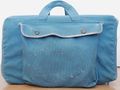
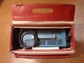
Tek 310a carrybag left.jpg | Carrying bag for 310, left | |||
Tek 310a carrybag top.jpg | Carrying bag for 310, top | |||
</gallery> | |||
'''310A''' | |||
<gallery> | |||
Tek_310A.jpg | Front view | |||
310A_right.jpg | Right internal | |||
310A_foldoff.jpg | Folded off internal | |||
310A_left.jpg | Left internal | |||
310A_top.jpg | Top internal | |||
310A_bottom.jpg | Bottom special slot to access sweep trigger tubes | |||
Tek_310A_Underside2.jpg | Bottom special slot to access sweep trigger tubes | |||
310A_back.jpg | Rear view | |||
Wellenkino 310a.jpg | 310A | |||
Tektronix-310a.jpg | 310A | |||
Tek 310a left internal.jpg | 310A Left Internal | |||
Tek 310a right internal.jpg | 310A Right Internal | |||
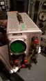
Tek_310a_right_internal_on.jpg | 310A Right Internal, operating | |||
Tek 310a top clean.jpg | 310A top | |||
Tek 310a rear2.jpg | 310A rear | |||
Tek 310a right internal2.jpg | 310A right internal | |||
Tek_310A_silicon_rectifiers.jpg | 310A with silicon rectifiers | |||
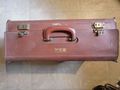
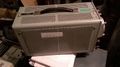
Tek ncr 310a case.jpg | Case for 310A | |||
Tek 310a in ncr case.jpg | 310A in case | |||
Tek 310a with case.jpg | Tek 310A with case | |||
Tek 310a carrybag exposed.jpg | 310A inside carrying bag, exposed cushion | |||
warranty.jpg | indefinite warranty to the Tektronix manufactured transformer | |||
Tek_310a_cl.jpg | |||
</gallery> | |||
'''Hickok AN/USM89B''' | |||
<gallery> | <gallery> | ||
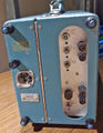
ANUSM89B_1.jpeg | Front view | |||
ANUSM89B_2.jpeg | Side view | |||
ANUSM89B_3.jpeg | Type plate | |||
</gallery> | |||
==Components== | |||
{{Parts|310}} | |||
{{Parts|310A}} | |||
==References== | |||
<references /> | |||
</ | |||
[[Category:Monolithic tube scopes]] | [[Category:Monolithic tube scopes]] | ||
Latest revision as of 11:27, 29 January 2024

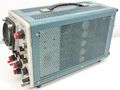
The Tektronix 310 is a compact portable oscilloscope, designed by Frank Hood and John Kobbe, that was introduced in 1955.
It is a 4 MHz single-trace, single-timebase scope with a 3" (7.5 cm) round CRT.
A revised version, the 310A, was introduced in 1959. While the 310 used printed-circuit boards, the 310A returned to ceramic strip construction in the interest of reliability. Is this the only time that a Tek design was moved from PCB back to ceramic strip?
The Hickok company produced a clone of the 310A under a US military contract as the AN/USM89B.
Key Specifications
| Bandwidth | 4 MHz (3.5 MHz below 0.1 V/Div, AC coupled) |
|---|---|
| Rise time | 90 ns (100 ns below 0.1 V/Div, AC coupled) |
| Sweep | 0.5 μs/Div to 0.2 s/Div 1–2–5 |
| Deflection | 10 mV/Div to 50 V/Div, 1–2–5 (below 0.1 V/Div only AC coupled) |
| Input impedance | 1 MΩ // 40 pF |
| X input | 1.5 V/Div (variable down), 500 kHz, 100 kΩ |
| Z input | 20 Vp-p at rear "CRT Cathode" binding post |
| Calibrator | 50 mVp-p to 100 Vp-p, 1–2–5; 1 kHz |
| Power | 175 W |
P2 phosphor was standard. P1, P7 and P11 were also available.
Links
- Richard Sears: Tektronix 310 and 310A
- A Tek 310 restoration @ YouTube: Part 1 / Part 2
Documents Referencing 310
| Document | Class | Title | Authors | Year | Links |
|---|---|---|---|---|---|
| IBM 223-6725-2.pdf | Application Note | Tektronix oscilloscopes (IBM Customer Engineering Manual) | 1960 | 310 • 310A • 531 • 531A • 535 • 535A • 545A • B • C • CA • D • G |
Documents Referencing 310A
| Document | Class | Title | Authors | Year | Links |
|---|---|---|---|---|---|
| IBM 223-6725-2.pdf | Application Note | Tektronix oscilloscopes (IBM Customer Engineering Manual) | 1960 | 310 • 310A • 531 • 531A • 535 • 535A • 545A • B • C • CA • D • G |
Internals
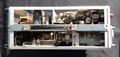
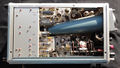
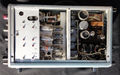
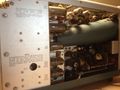
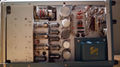
The scope cabinet was hinged to allow it to be opened like a book and operated for access to the circuitry for service purposes.
Cooling
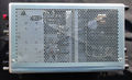
The 310 is a tube scope and consumes 175 watts, but it does not have a fan. It therefore tends to run hot, particularly when used in a hot environment with still air. It has a 74 °C (165 °F) thermal cutoff switch in series with the primary of the power transformer.
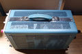
For extended use in one place, a tilted fan base, the FB310 (part number 016-012) was available. The fan base blows air upward through the perforated bottom panel of the 310. While the scope had universal primary wiring options, the fan base did not. Separate models were available for 115 VAC or 230 VAC operation.
The scope has feet on the rear panel to allow it to be operated on the floor with the front panel facing up, but the manual warns against prolonged operation in this orientation.
Components
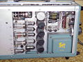
The 310 is a nearly true pure vacuum-tube scope, but in the power supply there are some silicon rectifiers, and there is one germanium point contact diode in the circuit.
Early examples of the Tektronix Type 310A used commodity 3WPx CRTs. At some point in production, they switched to the Tek-made T3100 CRT, which is compatible with the 3WP2.
310A changes
Unlike later Tek instruments, where the incremental model designated by an “A” suffix only occurred with a significant specification or performance enhancement, the original 310 and 310A were essentially identical. They even shared the same manual and schematics. The main difference was the wiring construction. needs to be checked - different tubes used according to the manuals
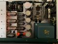
The original 310 pioneered the use of circuit board construction, rather than the trusted ceramic strip point to point wiring. The circuit boards were two-sided, however, Tektronix did not use through-hole plating although this had been introduced in 1947[1]. Rather, all of the holes for component mounting and interconnect contained a rivet which was expanded in a press before the components were installed in the board. The rivets themselves were not soldered to the copper foil traces, and relied on the pressure from the crimp to make contact. This proved to be extremely unreliable, with many intermittent connections resulting in high warranty- and after-warranty failure.
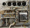
The 310A model essentially used the identical circuit design, but returned to the trusted ceramic strip construction method.
The 310A also replaced the selenium plate rectifiers in the power supply with silicon diodes. Tek offered a retrofit kit, to be installed in the service centers, to upgrade older scopes with selenium rectifiers.
Other changes during production
During the lifespan of the 310, Tek evolved its color scheme. The original 310 scopes had a case painted with a blue metallic hammer tone color. Later units moved to the crinkled “Tek Blue” color still in use today.
Like most old Tektronix devices the mains transformer holds an indefinite(!) warranty.
Price
$595 in 1955 ($6,700 in 2023 dollars)
Pictures
310
-
Right front
-
Front
-
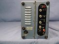
Rear
-
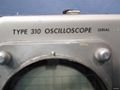
Model
-
Right rear
-
-
-
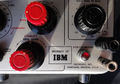
made for IBM
-
top inside
-
left inside
-
right internal
-
rear
-

bottom
-
right external
-

left external
-

310 on fan base
-
Carrying bag for 310, left
-

Carrying bag for 310, top


310A
-
Front view
-
Right internal
-
Folded off internal
-
Left internal
-
Top internal
-

Bottom special slot to access sweep trigger tubes
-
Bottom special slot to access sweep trigger tubes
-

Rear view
-
310A
-
310A
-
310A Left Internal
-

310A Right Internal
-
310A Right Internal, operating
-
310A top
-
310A rear
-
310A right internal
-
310A with silicon rectifiers
-
Case for 310A
-
310A in case
-

Tek 310A with case
-

310A inside carrying bag, exposed cushion
-
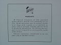
indefinite warranty to the Tektronix manufactured transformer
-


Hickok AN/USM89B
-
Front view
-
Side view
-
Type plate


Components
Some Parts Used in the 310
| Part | Part Number(s) | Class | Description | Used in |
|---|---|---|---|---|
| 12AT7 | 154-0039-00 | Vacuum Tube (Dual Triode) | dual high-gain triode | 161 • 180 • 310 • 310A • 315 • 316 • 360 • 502 • 502A • 511A • 512 • 513 • 513D • 514 • 514AD • 514D • 516 • 524 • 529 • RM529 • 544 • 546 • 547 • 556 • 565 • 570 • 3A2 • 75 • 3A75 • 1M1 • A • B • C • G • H • K • L • ML • M • N • K • R • S • Z |
| 12AU7 | 154-041 • 154-0041-00 • 154-0287-00 | Vacuum Tube (Dual Triode) | dual medium-μ triode | 104 • 104A • 122 • 160 • 161 • 162 • 181 • 190 • 310 • 310A • 316 • 317 • 3C66 • 502 • 502A • 507 • 511A • 512 • 516 • 517 • 517A • 524 • 526 • 535 • 536 • 545 • 545A • 545B • 547 • 549 • 555 • 561 • 564 • 570 • 575 • 581 • 581A • 585 • 585A • C • D • E • N • Q • Hickok 1825 |
| 12B4 | 154-044 • 154-0044-00 | Vacuum Tube (Triode) | power triode | 126 • 310 • 310A • 316 • 317 • 502 • 502A • 524 • 526 • 541 • 541A • 535 • 535A • 545 • 545A • 546 • 547 • 570 • 549 • 551 • 555 • 513 • 581 • 581A • 585 • 585A |
| 3WP | 154-0059-00 | CRT | series of flat-faced 3" mono-accelerator CRTs | 315 • 310 • 360 • Telequipment S31 |
| 5642 | 154-0051-00 • 154-0079-00 | Vacuum Tube (Diode) | directly-heated high-voltage rectifier | 310 • 310A • 316 • 317 • 360 • 453 • 502 • 502A • 503 • 504 • 506 • 513 • 515 • 516 • 524 • 529 • RM529 • 533 • 533A • 535 • 536 • 543 • 543A • 543B • 545 • 545A • 545B • 547 • 551 • 555 • 556 • 560 • 561 • 561A • 561S • 564 • 567 • 570 • 575 • 581 • 581A • 585 • 585A • 647 • 647A |
| 5651 | 154-052 • 154-0052-00 • 154-0288-00 | Gas Discharge Tube (Voltage regulator) | 87 V voltage reference | 128 • 160 • 310 • 310A • 502 • 503 • 504 • 511A • 512 • 516 • 517 • 524 • 526 • 531 • 531A • 535 • 536 • 541 • 541A • 543 • 543A • 543B • 545 • 545A • 545B • 570 • 549 • 581 • 581A • 585 • 585A |
| 6AL5 | 154-016 • 154-0016-00 • 154-0038-00 | Vacuum Tube (Dual Diode) | high-perveance dual diode | 163 • 181 • 190 • 1M1 • 310 • 310A • 315 • 316 • 317 • 3B1 • 3B1S • 3B2 • 3B3 • 3B5 • 502 • 502A • 503 • 511 • 511A • 512 • 516 • 517 • 517A • 524 • 526 • 535 • 535A • 545 • 545A • 549 • 551 • 565 • 570 • 581 • 581A • 585 • 585A • C • T • Telequipment D56 • Telequipment S52 |
| 6AN8 | 154-078 • 154-0078-00 | Vacuum Tube (Triode/Pentode) | triode-pentode combo | 310 • 310A • 316 • 317 • 360 • 502 • 502A • 516 • 517 • 517A • 526 • 565 • 570 • 575 • N |
| 6AQ5 | 154-017 • 154-0017-00 | Vacuum Tube (Pentode) | beam pentode | 310 • 310A • 316 • 360 • 507 • 511A • 512 • 517 • 517A • 524 • 536 • 570 • 575 |
| 6AU6 | 154-0022-00 • 157-0073-00 • 157-0059-00 • 154-0284-00 | Vacuum Tube (Pentode) | RF pentode | 107 • 160 • 181 • 190 • 60 • 2A60 • 72 • 3A72 • 3C66 • 310 • 310A • 316 • 317 • 360 • 502 • 502A • 506 • 511 • 511A • 512 • 513 • 516 • 517 • 517A • 524 • 526 • 529 • RM529 • 531 • 531A • 535 • 536 • 545 • 545A • 546 • 547 • 549 • 555 • 561 • 561A • 561S • 564 • 565 • 567 • 570 • 575 • 581 • 581A • 585 • 585A • 80 • C • CA • Q |
| 6BH6 | 154-0026-00 • 154-0285-00 | Vacuum Tube (Pentode) | pentode | 130 • 162 • 310 • 310A • 512 • 517 • 517A • 524 • Nelson-Ross PSA-011 |
| 6BQ7A | 154-028 • 154-0028-00 • 157-0022-00 • 157-0003-00 | Vacuum Tube (Dual Triode) | dual triode | 107 • 163 • 181 • 310 • 315 • 316 • 360 • 524 • 531 • 532 • 535 • 536 • 541 • 545 • 570 • T |
| 6CL6 | 154-031 • 154-0031-00 • 154-0286-00 | Vacuum Tube (Pentode) | 7.5 W power pentode | 132 • 310 • 310A • 316 • 317 • 515 • 524 • 525 • 531 • 535 • 535A • 545 • 545A • 545B • 549 • 570 • 581 • 581A • 585 • 585A • 3A74 |
| 6U8 | 154-0033-00 | Vacuum Tube (Triode/Pentode) | triode-pentode combo | 130 • 160 • 163 • 310 • 315 • 316 • 524 • 535 • 545 • T |
| T3100 | 154-0362-00 • 154-0363-00 • 154-0364-00 • 154-0365-00 • 154-0366-00 • 154-0058-01 • 154-0059-01 • 154-0060-01 • 154-0061-01 | CRT | 3" CRT | 310 • 310A • 315 • 360 |
Some Parts Used in the 310A
| Part | Part Number(s) | Class | Description | Used in |
|---|---|---|---|---|
| 12AT7 | 154-0039-00 | Vacuum Tube (Dual Triode) | dual high-gain triode | 161 • 180 • 310 • 310A • 315 • 316 • 360 • 502 • 502A • 511A • 512 • 513 • 513D • 514 • 514AD • 514D • 516 • 524 • 529 • RM529 • 544 • 546 • 547 • 556 • 565 • 570 • 3A2 • 75 • 3A75 • 1M1 • A • B • C • G • H • K • L • ML • M • N • K • R • S • Z |
| 12AU7 | 154-041 • 154-0041-00 • 154-0287-00 | Vacuum Tube (Dual Triode) | dual medium-μ triode | 104 • 104A • 122 • 160 • 161 • 162 • 181 • 190 • 310 • 310A • 316 • 317 • 3C66 • 502 • 502A • 507 • 511A • 512 • 516 • 517 • 517A • 524 • 526 • 535 • 536 • 545 • 545A • 545B • 547 • 549 • 555 • 561 • 564 • 570 • 575 • 581 • 581A • 585 • 585A • C • D • E • N • Q • Hickok 1825 |
| 12B4 | 154-044 • 154-0044-00 | Vacuum Tube (Triode) | power triode | 126 • 310 • 310A • 316 • 317 • 502 • 502A • 524 • 526 • 541 • 541A • 535 • 535A • 545 • 545A • 546 • 547 • 570 • 549 • 551 • 555 • 513 • 581 • 581A • 585 • 585A |
| 5642 | 154-0051-00 • 154-0079-00 | Vacuum Tube (Diode) | directly-heated high-voltage rectifier | 310 • 310A • 316 • 317 • 360 • 453 • 502 • 502A • 503 • 504 • 506 • 513 • 515 • 516 • 524 • 529 • RM529 • 533 • 533A • 535 • 536 • 543 • 543A • 543B • 545 • 545A • 545B • 547 • 551 • 555 • 556 • 560 • 561 • 561A • 561S • 564 • 567 • 570 • 575 • 581 • 581A • 585 • 585A • 647 • 647A |
| 5651 | 154-052 • 154-0052-00 • 154-0288-00 | Gas Discharge Tube (Voltage regulator) | 87 V voltage reference | 128 • 160 • 310 • 310A • 502 • 503 • 504 • 511A • 512 • 516 • 517 • 524 • 526 • 531 • 531A • 535 • 536 • 541 • 541A • 543 • 543A • 543B • 545 • 545A • 545B • 570 • 549 • 581 • 581A • 585 • 585A |
| 6AL5 | 154-016 • 154-0016-00 • 154-0038-00 | Vacuum Tube (Dual Diode) | high-perveance dual diode | 163 • 181 • 190 • 1M1 • 310 • 310A • 315 • 316 • 317 • 3B1 • 3B1S • 3B2 • 3B3 • 3B5 • 502 • 502A • 503 • 511 • 511A • 512 • 516 • 517 • 517A • 524 • 526 • 535 • 535A • 545 • 545A • 549 • 551 • 565 • 570 • 581 • 581A • 585 • 585A • C • T • Telequipment D56 • Telequipment S52 |
| 6AN8 | 154-078 • 154-0078-00 | Vacuum Tube (Triode/Pentode) | triode-pentode combo | 310 • 310A • 316 • 317 • 360 • 502 • 502A • 516 • 517 • 517A • 526 • 565 • 570 • 575 • N |
| 6AQ5 | 154-017 • 154-0017-00 | Vacuum Tube (Pentode) | beam pentode | 310 • 310A • 316 • 360 • 507 • 511A • 512 • 517 • 517A • 524 • 536 • 570 • 575 |
| 6AU6 | 154-0022-00 • 157-0073-00 • 157-0059-00 • 154-0284-00 | Vacuum Tube (Pentode) | RF pentode | 107 • 160 • 181 • 190 • 60 • 2A60 • 72 • 3A72 • 3C66 • 310 • 310A • 316 • 317 • 360 • 502 • 502A • 506 • 511 • 511A • 512 • 513 • 516 • 517 • 517A • 524 • 526 • 529 • RM529 • 531 • 531A • 535 • 536 • 545 • 545A • 546 • 547 • 549 • 555 • 561 • 561A • 561S • 564 • 565 • 567 • 570 • 575 • 581 • 581A • 585 • 585A • 80 • C • CA • Q |
| 6BH6 | 154-0026-00 • 154-0285-00 | Vacuum Tube (Pentode) | pentode | 130 • 162 • 310 • 310A • 512 • 517 • 517A • 524 • Nelson-Ross PSA-011 |
| 6CL6 | 154-031 • 154-0031-00 • 154-0286-00 | Vacuum Tube (Pentode) | 7.5 W power pentode | 132 • 310 • 310A • 316 • 317 • 515 • 524 • 525 • 531 • 535 • 535A • 545 • 545A • 545B • 549 • 570 • 581 • 581A • 585 • 585A • 3A74 |
| 6DJ8 | 154-0187-00 • 154-0305-00 | Vacuum Tube (Dual Triode) | dual triode | 132 • 161 • 310A • 316 • 317 • 502 • 502A • 503 • 504 • 506 • 515 • 516 • 519 • 526 • 529 • RM529 • 533 • 535 • 536 • 543 • 544 • 545 • 545A • 545B • 546 • 547 • 549 • 555 • 556 • 561A • 561S • 564 • 565 • 567 • 581 • 581A • 585 • 585A • 661 • 1A4 • 1S1 • 60 • 2A60 • 63 • 2A63 • 67 • 2B67 • 3A1 • 3A1S • 3A2 • 3A3 • 3A6 • 3A7 • 72 • 3A72 • 75 • 3A75 • 4S2 • 51 • 3B1 • 3B1S • 3B2 • 3B3 • 3B4 • 3M1 • 3S76 • 3T77 • 3T77A • 9A1 • 9A2 • 1121 • 80 • 81 • 82 • 86 • B • O • W • Z • Telequipment D56 • Telequipment S32A • Telequipment D52 • S-311 • Telequipment TD51 • Telequipment S52 • Telequipment S51 • Telequipment Type A • TU-4 |
| 8425 | 154-0022-07 | Vacuum Tube (Pentode) | RF pentode | 3A72 • 310A • 317 • 526 • Q |
| T3100 | 154-0362-00 • 154-0363-00 • 154-0364-00 • 154-0365-00 • 154-0366-00 • 154-0058-01 • 154-0059-01 • 154-0060-01 • 154-0061-01 | CRT | 3" CRT | 310 • 310A • 315 • 360 |