3A74: Difference between revisions
No edit summary |
No edit summary |
||
| (12 intermediate revisions by 4 users not shown) | |||
| Line 2: | Line 2: | ||
title=Tektronix 3A74| | title=Tektronix 3A74| | ||
summary=2 MHz four channel vertical amp| | summary=2 MHz four channel vertical amp| | ||
image= | image=Tek_3A74_front_crop.jpg | | ||
caption=3A74 front| | caption=3A74 front| | ||
introduced=1962 | | introduced=1962 | | ||
| Line 12: | Line 12: | ||
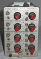
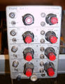
The '''Tektronix Type 3A74''' is a four-channel vertical plug-in [[introduced in 1963]] for | The '''Tektronix Type 3A74''' is a four-channel vertical plug-in [[introduced in 1963]] for | ||
[[560-series scopes]]. The bandwidth is DC to 2 MHz. | [[560-series scopes]]. The bandwidth is DC to 2 MHz. | ||
A modified 3A74 MOD 730A (with a charge pre-amplifier on channel 1 to accommodate piezoelectric pressure transducers) | |||
was part of the [[Engine Analyzer]] package. | |||
{{BeginSpecs}} | {{BeginSpecs}} | ||
| Line 23: | Line 26: | ||
==Internals== | ==Internals== | ||
Each input signal passes through | Each input signal passes through switchable input attenuators and then into a cathode-follower | ||
switchable input attenuators and then into a cathode-follower made from a [[7586]] | made from a [[7586]] Nuvistor triode driving a PNP differential amplifier. The output of this | ||
Nuvistor triode | |||
differential amplifier, for each of the four channels, passes through a diode-based | differential amplifier, for each of the four channels, passes through a diode-based | ||
analog signal switching network (multiplexer). The output of that multiplexer drives the output amplifier, | analog signal switching network (multiplexer). The output of that multiplexer drives the output amplifier, | ||
| Line 31: | Line 33: | ||
are generated by a transistor-based ring oscillator, a four-state cyclic state machine. | are generated by a transistor-based ring oscillator, a four-state cyclic state machine. | ||
This allows each of the input signals to be traced on the screen, one after another. | This allows each of the input signals to be traced on the screen, one after another. | ||
The 3A74 uses Tek-made 185 Ω [[potentiometers]] in for the VAR GAIN controls. | |||
These can be a [[:Category:Repair_issues|maintenance issue]]. | |||
The 3A74 contains a total of eight 7586 [[Nuvistor]]s. | |||
==Links== | ==Links== | ||
* [http://www.amplifier.cd/Test_Equipment/Tektronix/Tektronix_other/3A74.htm Tek 3A74 | * [http://www.amplifier.cd/Test_Equipment/Tektronix/Tektronix_other/3A74.htm Tek 3A74 @ amplifier.cd] | ||
* http://www.barrytech.com/tektronix/vintage/tek3a74.html | * [http://www.barrytech.com/tektronix/vintage/tek3a74.html Tek 3A74 @ barrytech.com] | ||
* [https://www.radiomuseum.org/r/tektronix_3a74_plug_in_unit.html Tek 3A74 @ radiomuseum.org] | |||
==Pictures== | ==Pictures== | ||
<gallery> | <gallery> | ||
Tek_3A74_front.jpg | |||
Tek 3a74 1.JPG|Front Side | |||
Tek 3a74 2.JPG|Rear Side | |||
Tek 3a74 3.JPG|Left Side | |||
Tek 3a74 4.JPG|Right Side | |||
3a74 block diagram.png|Block Diagram | |||
3a74 switching.png|Channel Switching | |||
3a74 amp schem.png|Amplifier | |||
Tek 311-0304-00 pot.jpg|VAR GAIN potentiometer, sometimes problematic | |||
Tek 3a74 s1.jpg | |||
Tek 3a74 s2.jpg | |||
Tek 3a74 s3.jpg | |||
Tek 3a74 s4.jpg | |||
Tek 3a74 s5.jpg | |||
Tek 3a74 front.jpg | |||
Tek 3a74 right.jpg | |||
Tek 3a74 left.jpg | |||
Tek 3a74 top.jpg | |||
Tek 3a74 bottom.jpg | |||
Tek 3a74 rear.jpg | |||
</gallery> | </gallery> | ||
[[Category:560 series plugins]] | [[Category:560 series plugins]] | ||
Revision as of 10:20, 12 December 2018
Template:Plugin Sidebar 2 The Tektronix Type 3A74 is a four-channel vertical plug-in introduced in 1963 for 560-series scopes. The bandwidth is DC to 2 MHz.
A modified 3A74 MOD 730A (with a charge pre-amplifier on channel 1 to accommodate piezoelectric pressure transducers) was part of the Engine Analyzer package.
Key Specifications
| Bandwidth | 2 MHz |
|---|---|
| Input impedance | 1 MΩ // 47 pF |
| Deflection | 20 mV/Div to 10 V/Div in 1–2–5 sequence |
| Features |
|
Internals
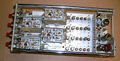
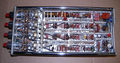
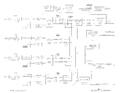
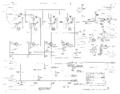
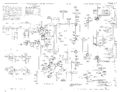
Each input signal passes through switchable input attenuators and then into a cathode-follower made from a 7586 Nuvistor triode driving a PNP differential amplifier. The output of this differential amplifier, for each of the four channels, passes through a diode-based analog signal switching network (multiplexer). The output of that multiplexer drives the output amplifier, which is part transistor, part tube. The one-hot select line signals for the multiplexer are generated by a transistor-based ring oscillator, a four-state cyclic state machine. This allows each of the input signals to be traced on the screen, one after another.
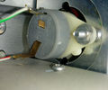
The 3A74 uses Tek-made 185 Ω potentiometers in for the VAR GAIN controls. These can be a maintenance issue.
The 3A74 contains a total of eight 7586 Nuvistors.
Links
Pictures
-
-
Front Side
-

Rear Side
-
Left Side
-
Right Side
-
Block Diagram
-
Channel Switching
-
Amplifier
-
VAR GAIN potentiometer, sometimes problematic
-

-

-

-

-

-

-

-

-

-

-


