468/Repairs
ROM rot
Many 468s used Mostek MK36000 masked ROMs that can suffer from "ROM rot". It may be necessary to replace the 160-0459-01 and 160-0759-01 ROMs with 2764 EPROMs through a 2364/2764 adapter. Another option might be using the MCM68766 EPROM.
-
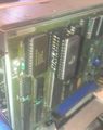
replaced ROM by 2764 with homemade 2364/2764 adapter
-
Result of bad ROM by verification-check.


Service ROM
- TEK 468 Service Rom (067-0989-00) file - For using as per TEK 468 Service Manual (test requires removing the A/D converter U456 and plugging in a 74LS393 in the socket underneath).
A16 STORAGE-DISPLAY Circuit Board Replacement ERROR in SERVICE Manual Schematic and Parts list
I recently installed a replacement A16 board and this cured part of my original problem, but still something was not right.
The original problem was with the storage display being blanked and not visible, the "new" board cured that issue. When I installed the new board, in Non-Storage mode everything worked perfect, as before. However, when I selected Storage mode, I saw a partial trace, but could not horizontally center the trace. The storage trace was about 2/3 visible with the horizontal pot fully CCW and disappeared completely with the Horz. control centered. In addition, the cursors were visible, but acted in a bizarre manner, not adjusting fully to the entire range of the screen and crowded near the bottom of the display. Basically, the storage display was shifted down and right and the cursors were forced to the bottom of that area. So the problem lay in the Storage Position portion of the circuit.
The Storage Display Troubleshooting chart contains a block that states "check U559-7 at 7.5 V and U559-1 at -7.5 V. . . . ". indicating that U559 is designed to produce a +7.5 V and -7.5 V Reference voltage, however, on my unit, U559 was outputting a bit over 5 V on the V Ref Pins. This voltage is obviously critical to the storage display portion, the Reference voltage was low at all IC's across the entire A16 board. Since I obtained this board from a known good, working scope, I found it hard to believe that U559 could be bad. I concluded that there must be something external to A16 was causing the Reference voltage to be so low.
Voltage @ U559 (as received) before W250 was lifted:
- U559-1 -5.064 V
- U559-7 +5.064 V
Looking at the schematic, I saw a Service Jumper W250 in the +7.5V circuit, so I decided to disconnect this jumper, hoping to see some sort of change. This simple act fixed the horizontal position, vertical position and cursor problems immediately. All that was needed were a few minor adjustments to the trimmers.
Closer examination of the original A16 board revealed that there was no jumper in this position and never had been one installed on the board.
Voltage @ U559 after W250 was lifted/removed:
- U559-1 -7.494 V
- U559-7 +7.494 V
The position controls are connected slightly different on the early and late models, this is clearly shown in the Vertical Amp schematics.
- "Late" models (s/n B040000 & up) have 5 V supplied to Pin 3 of the Vertical Position pots from another source on the Vertical Amp board.
- "Early" model (s/n B039999 & down)use the 7.5 V Reference from A16 routed through W250 to supply Pin 3 of the Vertical Position pots.
Therefore:
- A16 "Early" model (s/n B039999 & down) use W250.
- A16 "Late" models (s/n B040000 & up) do not use W250 and have empty pads where W250 would have been installed.
The +5 V from the Vertical Position Pots was opposing the +7.5 V that was being fed from U559B and through W250. The also reduced the output of U559A as well, since that part of the Op-Amp is a simple inverter.
My Service Manual Schematic does not show a S/N break for W250 on A16. In addition the electrical parts list shows this part being used on all units.
To compound the issue, my specific unit was "Made in Holland", so I could not tell for certain which schematic applied. Evidently, this particular unit is a "Late" pattern unit and the board that I obtained was one from an "Early" pattern unit.