567: Difference between revisions
(added photo) |
No edit summary |
||
| Line 12: | Line 12: | ||
in that configuration it provides the same functionality that | in that configuration it provides the same functionality that | ||
a 561 provides. | a 561 provides. | ||
The 6R1 and 6R1A digital units have several different operating | |||
modes. These modes can be classified in to time measurement or | |||
voltage measurement. One time measurement mode, for example, | |||
shows the time delay between the rising pulse edge on input A | |||
and the falling pulse edge on input B. This is useful for measuing | |||
the speed of a logic gate such as an inverter. One of the voltage | |||
measurement modes displays the difference between the input A voltage | |||
at on time and the input A voltage at some other time. This is | |||
useful for measuring the peak-to-peak amplitude of a signal. | |||
The mechanisms used by the digital unit are a sample and hold | |||
circuit, a comparator, a counter, and a switched tap voltage divider. | |||
The digital unit takes its input from the vertical signal produced | |||
by the sampling unit. Therefore, it operates on a low-speed | |||
signal, somewhat similar to the intermediate frequency (IF) in | |||
a superheterodyne radio. The user positions two cursors along the | |||
X-axis. These cursors define two times and two voltages. | |||
<gallery> | <gallery> | ||
Image:567_front.jpg|Front view | Image:567_front.jpg|Front view | ||
</gallery> | </gallery> | ||
Revision as of 12:43, 26 January 2010
The Tektronix 567 is a sampling scope made by Tektronix in the mid 1960's, first sold in 1963. It has a digital plug-in unit, the 6R1 or 6R1A, that can be used to measure waveform characteristics such as rise time. This digital unit provides a go/no-go output based on waveform characteristics. This feature make the 567 particularly useful in production testing, for example, binning logic gates based on their speed. The 567 came after the 661 and before the 568.
The 567 has three plug-in compartments. The left compartment holds a 3S-series sampling vertical unit. The center compartment holds a 3T-series sampling sweep unit. The right compartment holds the digital unit. It is possible to operate a 567 without the digital unit but in that configuration it provides the same functionality that a 561 provides.
The 6R1 and 6R1A digital units have several different operating modes. These modes can be classified in to time measurement or voltage measurement. One time measurement mode, for example, shows the time delay between the rising pulse edge on input A and the falling pulse edge on input B. This is useful for measuing the speed of a logic gate such as an inverter. One of the voltage measurement modes displays the difference between the input A voltage at on time and the input A voltage at some other time. This is useful for measuring the peak-to-peak amplitude of a signal.
The mechanisms used by the digital unit are a sample and hold circuit, a comparator, a counter, and a switched tap voltage divider. The digital unit takes its input from the vertical signal produced by the sampling unit. Therefore, it operates on a low-speed signal, somewhat similar to the intermediate frequency (IF) in a superheterodyne radio. The user positions two cursors along the X-axis. These cursors define two times and two voltages.
-
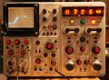
Front view
