575: Difference between revisions
No edit summary |
|||
| Line 59: | Line 59: | ||
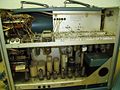
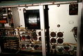
Tek 575 internal.jpg | Tek 575 internal.jpg | ||
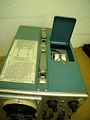
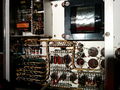
Tek 575 rear.jpg | Tek 575 rear.jpg | ||
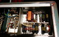
Tek 575 bottom.jpg|Bottom | Tek 575 bottom.jpg | Bottom | ||
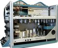
Tek 575 bottom rear.jpg|Bottom Rear | Tek 575 bottom rear.jpg | Bottom Rear | ||
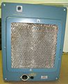
Tek 575 hvps 1.jpg|High-Voltage Power Supply | Tek 575 hvps 1.jpg | High-Voltage Power Supply | ||
USA Tektronix 575 Front RAW.jpg | |||
USA Tektronix 575 InsideR0.jpg | |||
</gallery> | </gallery> | ||
===Schematics=== | ===Schematics=== | ||
Revision as of 15:46, 7 March 2017

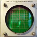
The Tektronix 575 is a curve tracer for transistors, introduced in March 1957. It can be thought of as being composed of three modules: an X-Y display, a step source, and a collector sweep source.
Key Specifications
- please add
Internals
X-Y display
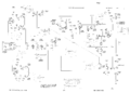
The vertical and horizontal amplifiers are very similar, using the two halves of a 6CG7 dual-triode tube as the output amplifier. The CRT has -1700 V on the cathode and +2500 V on the anode. The HV power supply uses two 5642 rectifier tubes.
It is possible to use the 575 as an X-Y monitor. The vertical and horizontal range switches have settings for external input, at 0.1 V/div sensitivity.
Step Source
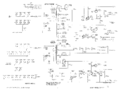
This uses a gated Miller integrator to generate controlled steps. The result is a staircase waveform, which generates different traces in the the family of I-V curves of the transistor.
Collector Sweep
Power from the mains goes through an isolation transformer and a variac and is rectified by germanium diodes to produce the collector sweep voltage. The isolation transformer has two pairs of secondary taps, one for high voltage (0 to 200 V) and low current, the other for low voltage (0 to 20 V) and high current. The maximum power that can be delivered to the transistor in either mode is approximately 200 Watts.
575 with Mod 122C has extended collector sweep voltage to 400 V.
Rectifiers
Early 575 versions used selenium rectifiers. A kit for conversion to silicon diodes was available and is documented in the back of the manual.
The 575 has a thermal cutoff.
Type 175 High Current Adaptor

The 575 can be paired with a 175 for high current device measurements.
Links
- "A Power Curve Tracer At Surplus Prices" by Dennis L. Feucht (PDF)
- Some Transistor Measurements Using the Type 575
- Tek 575 @ oscilloscopemuseum.com
Pictures
-
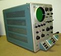
575 w/o Mod 122C
-
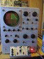
575 w Mod 122C
-
-
-
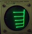
575 testing a tunnel diode
-
-
-
-
Bottom
-
Bottom Rear
-
High-Voltage Power Supply
-

-


Schematics
-
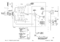
Unmodified Collector Supply
-
Collector Supply Rectifier with MOD122C
-
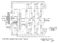
Main Power Supply
-
Step Generator
-
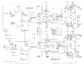
Amplifiers
-
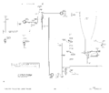
CRT Circuit


