585: Difference between revisions
No edit summary |
No edit summary |
||
| Line 37: | Line 37: | ||
The main difference is the impedance of the signal that passes | The main difference is the impedance of the signal that passes | ||
through the interface from the plug-in to the mainframe. | through the interface from the plug-in to the mainframe. | ||
In 530/540/550-series scopes, the plug-in expects the mainframe to be a high impedance load | In 530/540/550-series scopes, the plug-in expects the mainframe to be a high impedance load, | ||
driving tube grids in the mainframe. | |||
The [[580 Series plug-in interface]], on the other hand, presents a differential transmission line | |||
input with an impedance of 93 Ω per side, going into the first distributed amplifier stage. The | |||
other end of this transmission line is returned to the plug-in for termination and biasing. | |||
The [[580 Series plug-in interface|pin-out of the interface connector]] is also different, | The [[580 Series plug-in interface|pin-out of the interface connector]] is also different, | ||
the 580-series pin-out being essentially flipped 180° from its | the 580-series pin-out being essentially flipped 180° from its 530/540/550 series counterparts | ||
530/540/550 series counterparts (''Signal Out'' is between pins 14 and 16 as opposed to between pins 1 and 3, etc.) | (''Signal Out'' is between pins 14 and 16 as opposed to between pins 1 and 3, etc.) | ||
The [[81|Type 81]] adapter allows the use of letter-series and 1-series plug-ins in a 585. | The [[81|Type 81]] adapter allows the use of letter-series and 1-series plug-ins in a 585. | ||
| Line 51: | Line 53: | ||
made of a pair of miniature dual triode tubes. | made of a pair of miniature dual triode tubes. | ||
Starting at serial number 1071, the | Starting at serial number 1071 (and sometimes retrofitted to earlier instruments), the dual-triode | ||
10 mA [[tunnel diodes|tunnel diode]] | Schmitt trigger circuit was replaced by a 10 mA [[tunnel diodes|tunnel diode]] AC-coupled to the | ||
transistor. The | base-emitter junction of an [[OC171]] germanium PNP transistor as a pulse amplifier. | ||
The slower "B" timebase uses a Schmitt trigger circuit. | |||
=== Vertical Signal Path === | === Vertical Signal Path === | ||
Like the [[545]], [[551]], and [[555]], the 585 uses two [[distributed amplifier]]s in the vertical | Like the [[545]], [[551]], and [[555]], the 585 uses two [[distributed amplifier]]s in the vertical signal path, | ||
signal path, one with seven differential [[6DJ8]] stages driving a helically-wound, differential [[delay line]], | one with seven differential [[6DJ8]] stages driving a helically-wound, differential [[delay line]], followed by | ||
followed by a five-stage differential distributed driver amplifier and a [[7699]] power stage driving the CRT. | a five-stage differential distributed driver amplifier and a [[7699]] dual tetrode power stage driving the CRT. | ||
Unlike the other 500-series scopes, the 585 uses a CRT with [[distributed vertical deflection plates]], | Unlike the other 500-series scopes, the 585 uses a CRT with [[distributed vertical deflection plates]], | ||
the [[T581]], enabling it to have both high sensitivity and fast risetime. | the [[T581]], enabling it to have both high sensitivity (~5 V/cm vertically) and fast risetime, | ||
however, limiting vertical deflection to slightly over 4 cm. Total acceleration voltage is 10 kV. | |||
Several improvements were published for the 585 circuitry, including the enhanced trigger circuit. | Several improvements were published for the 585 circuitry, including the enhanced trigger circuit. | ||
If all of those changes are applied to a 585, it is essentially a 585A. | If all of those changes are applied to a 585, it is essentially a 585A. | ||
After serial number 2585, the back termination of the final distributed amplifier output was made adjustable. | |||
The manual says this (field-installable) modification is "required for proper operation of plug-ins with numbers above | |||
[[81|Type 81]]". | |||
===Power Supply=== | ===Power Supply=== | ||
Revision as of 07:37, 17 June 2018

The Tektronix 585 is a 100 MHz 580-Series scope that Tektronix introduced in 1959. The 585A facelift model was introduced in 1963 and discontinued after 1971.
At 100 MHz (later slightly down-rated) with the Type 80 plug-in and up to 85 MHz with the dual-channel Type 82, the 585 was the highest-speed general purpose scope of Tek's tube scope era (the 1 GHz 519 was specialized with no vertical amplifier).
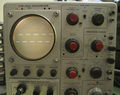
The 585's front panel layout is almost identical to the 545A that came out at the same time. The 585 also shares internal construction and circuits such as the power supply with the 535/545 line of scopes.
Key Specifications
| Rise time | 3.5 ns with Type 80 plugin and P80 probe |
|---|---|
| Timebase A | 50 ns/Div to 2 s/Div, 1−2−5, variable ×2.5, magnifier ×5, single sweep; X input |
| Timebase B | 2 μs/Div to 1 s/Div, 1−2−5, can delay timebase A by 1 μs to 10 s |
| CRT | T581, distributed vertical deflection plates, 10 kV acceleration |
| Outputs | A Sawtooth, A Gate, B Gate, Calibrator (0.2 mV to 100 Vp-p, 1−2−5) |
585A differences
The 585A uses a tunnel-diode trigger circuit (see below), adds HF Sync and AC LF reject modes to the timebase A trigger selector, and adds a trace rotation coil.
Internals
Plug-in Interface
The 585 uses 580-series plug-ins which look like letter-series and 1-series plug-ins but are electrically different. The main difference is the impedance of the signal that passes through the interface from the plug-in to the mainframe. In 530/540/550-series scopes, the plug-in expects the mainframe to be a high impedance load, driving tube grids in the mainframe. The 580 Series plug-in interface, on the other hand, presents a differential transmission line input with an impedance of 93 Ω per side, going into the first distributed amplifier stage. The other end of this transmission line is returned to the plug-in for termination and biasing. The pin-out of the interface connector is also different, the 580-series pin-out being essentially flipped 180° from its 530/540/550 series counterparts (Signal Out is between pins 14 and 16 as opposed to between pins 1 and 3, etc.)
The Type 81 adapter allows the use of letter-series and 1-series plug-ins in a 585.
Trigger Circuit
The original 585 (up to serial number 1070) has an "A" trigger circuit that has a differential trigger amplifier made of a pair of 6EW6 miniature pentodes, followed by a Schmitt trigger made of a pair of miniature dual triode tubes.
Starting at serial number 1071 (and sometimes retrofitted to earlier instruments), the dual-triode Schmitt trigger circuit was replaced by a 10 mA tunnel diode AC-coupled to the base-emitter junction of an OC171 germanium PNP transistor as a pulse amplifier.
The slower "B" timebase uses a Schmitt trigger circuit.
Vertical Signal Path
Like the 545, 551, and 555, the 585 uses two distributed amplifiers in the vertical signal path, one with seven differential 6DJ8 stages driving a helically-wound, differential delay line, followed by a five-stage differential distributed driver amplifier and a 7699 dual tetrode power stage driving the CRT.
Unlike the other 500-series scopes, the 585 uses a CRT with distributed vertical deflection plates, the T581, enabling it to have both high sensitivity (~5 V/cm vertically) and fast risetime, however, limiting vertical deflection to slightly over 4 cm. Total acceleration voltage is 10 kV.
Several improvements were published for the 585 circuitry, including the enhanced trigger circuit. If all of those changes are applied to a 585, it is essentially a 585A.
After serial number 2585, the back termination of the final distributed amplifier output was made adjustable. The manual says this (field-installable) modification is "required for proper operation of plug-ins with numbers above Type 81".
Power Supply
The 585 power supply is similar to other Tek scopes of the era such as the 549. A linear regulator with a 5651 reference tube, a 12AX7/6AU6 error amplifier and three parallel 12B4 series pass tubes produces −150 V. This is the only adjustable rail, all other regulated voltages are referenced to it. The +100 V and +350 V regulators use half a 6080 each as the pass element, the +225 V two. In the +500 V path, a 12B4 performs this function. The unregulated +325 V input to the 225 V supply is used to supply the HV oscillator, a 6AU5.
A transistor-based regulator supplies a +12.6 V heater voltage to the plug-in.
A 6N045 delay relay controls a multi-contact relay to switch supply voltages on only after the tubes are warmed up. When the main relay engages, the delay relay is cut out so it will be ready to delay again even after a quick interrupt in power input.
The 585 contains a 53°C (128°F) thermal cutoff.
Semiconductors
The 585 uses semiconductor diodes as rectifiers and Germanium transistors in the 12 V power supply.
Rackmount Versions
Rackmount versions were also made, the RM585 and RM585A.
Prices
| 585 | 585A | ||||
| Year | 1959 | 1962 | 1963 | 1965 | 1971 |
|---|---|---|---|---|---|
| Catalog price | $1,675 | $1,725 | $1,725 | $1,725 | $2,400 |
| 2018 value | $14,330 | $14,220 | $14,040 | $13,640 | $14,760 |
Pictures
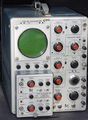
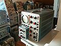
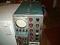
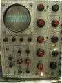
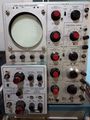
585 non-A
-
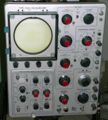
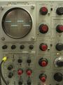
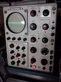
585 with Type 81 Adapter and Type CA plug-in
-
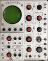
585 with Type 81 Adapter and Type CA plug-in
-
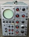
585 with Type 82
-
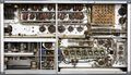
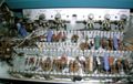
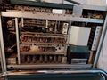
585 bottom view
-
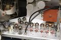
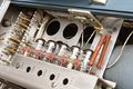
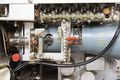
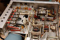
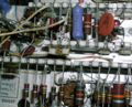
Distributed delay line driver amplifier
-
Distributed delay line driver amplifier (bottom). Plug-in interface connector to the left.
-
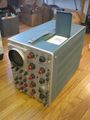
585 left side
-
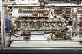
Vertical amplifier (post-delay 5-stage distributed amplifier)
-
Vertical amplifier (5-stage dist amp, power output stage)
-
Rectifiers
-
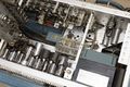
Time Base A
-
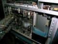
585 top view
-
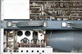
585 rear from above, handle and HV cover removed
-
-
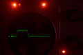
585 displaying a ~150 ns pulse at 100 Hz repetition rate at fastest timebase setting
-
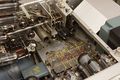
585 delay line driver distributed amplifier in operation
-

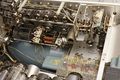
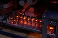
585 power supply (center) and timebase B (left) in operation
-
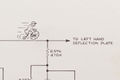
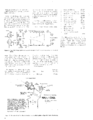
Cyclist cartoon in horizontal amplifier schematic


585A
-
-
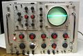
585A with 82
-
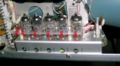
585A trigger circuit
-
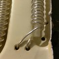
White plastic clip holds tunnel diode for triggering
-
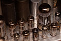
Inside view shows regulator tubes
-
Distributed vertical amplifier
-

T5810P31 distributed deflection plates
-
-
-
585A delay line
-
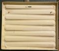
585A delay line
-
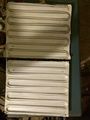
585A delay line
-
-
-
585 with TRIGGER SOURCE switch upgraded to 585A design
-
585A on cart
-
585A with 81A and Hickok plug-in
-
-
Direct Connection to CRT (from 1964 Service Scope)


RM585A
-
RM-585A
