661: Difference between revisions
No edit summary |
No edit summary |
||
| Line 17: | Line 17: | ||
Based on the available schematics, the 661 appears to have been designed in 1961. During what years was it manufactured? Why is it that the 661 has a dedicated high-speed coaxial interface between the sampling unit and the timing unit and later 560-series sampling systems (3S2, 3T77A, etc.) are able to simply use the regular plug-in connector and mainframe wiring harness for routing trigger and timing signals between the two units? | Based on the available schematics, the 661 appears to have been designed in 1961. During what years was it manufactured? Why is it that the 661 has a dedicated high-speed coaxial interface between the sampling unit and the timing unit and later 560-series sampling systems (3S2, 3T77A, etc.) are able to simply use the regular plug-in connector and mainframe wiring harness for routing trigger and timing signals between the two units? | ||
Some 661s have a multipin connector on the rear panel, perhaps to allow the 661 to be interfaced to low speed data acquisition equipment | |||
or a computer. | |||
* [http://bama.edebris.com/manuals/tek/661 661 manual on BAMA] | * [http://bama.edebris.com/manuals/tek/661 661 manual on BAMA] | ||
Revision as of 13:44, 10 April 2010
The Tektronix 661 is a sampling scope that was made by Tektronix starting in 1961. It accepts two plug-ins: a sampling unit and a timing unit. At least three sampling units were made, the 4S1 (0.35 ns rise time) and the 4S2 (0.1 ns rise time), and the 4S3. At least three timing units were made, the 5T1, 5T1A, and the 5T3. The timing units use tunnel diode triggering. Two coaxial cables in the scope connect the sampling unit to the timing unit. One cable sends the trigger pickoff signal from the sampling unit to the timing unit. The other cable sends the timing signal from the timing unit to the sampling unit, telling it when to sample.
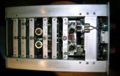
The mainframe of the 661 is quite simple. It contains a calibration signal generator and a high-speed pulse generator, but otherwise it is just a low-speed X-Y indicator. The total CRT accelerating voltage is 3kV and the vertical and horizontal amplifiers are relatively mild differential amplifiers made of 6DJ8 tubes. The sophistication of the 661 is all in the plug-ins. The signal from the calibration generator is available on the front panel and is also sent to the timing generator through the multi-pin plug-in connector. This allows the timing plug-ins to select "CAL" as a trigger source. In this mode, the calibration generator can be used as the stimulus for the device under test. In many situations, this eliminates the need for external triggering. When the timing unit triggers, a pulse is sent to the high-speed delayed pulse generator in the 661, which triggers and outputs a positive 250mV pulse about 400 nanoseconds long. The rising edge of this pulse is very fast.
The 4S1 is a dual-trace sampling unit for the 661. Each channel has a trigger pickoff, a delay line, and a sampler. The sampling pulses for each channel are generated by a step recovery diode are are fed to a sampling bridge made with of GaAs diodes. These diodes are fragile and exact replacements are hard to find. People have improvised replacements using modern integrated Schottky diodes such as those in HP/Agilent's HSMS-28x series. The 4S1 has a dual-trace mode, where the A waveform and the B waveform are both displayed in the time domain at the same time with a single trigger source and a single equivalent-time sweep rate. Another mode of is called "A vert/B horiz". This mode is used in conjunction with an X-Y mode switch on the panel of the 661 to allow arbitrary external control of the sampling point instead of a linear or random equivalent-time sweep.
The 4S2 is very similar to the 4S1, but has faster rise time. This is partly due to the elimination of the trigger pickoff and delay line on each channel. Since the 4S2 does not provide a pickoff signal to the timing plug-in, when using a 4S2 only one of the coaxial interconnect cables in the 661 carries a signal. The timing unit gets the trigger signal either from external input or from the internal pulse source in the 661.
Based on the available schematics, the 661 appears to have been designed in 1961. During what years was it manufactured? Why is it that the 661 has a dedicated high-speed coaxial interface between the sampling unit and the timing unit and later 560-series sampling systems (3S2, 3T77A, etc.) are able to simply use the regular plug-in connector and mainframe wiring harness for routing trigger and timing signals between the two units?
Some 661s have a multipin connector on the rear panel, perhaps to allow the 661 to be interfaced to low speed data acquisition equipment or a computer.
- 661 manual on BAMA
- 4S1 manual without schematics
- 4S1 schematics
- 4S2 schematics
- 4S2 complete manual
- 5T1A manual
- 5T3 manual
-
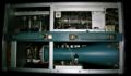
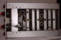
top internal view
-
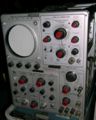
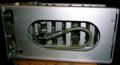
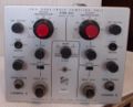
front view
-
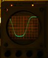
trace with 10 samples/cm and 2x horizontal expansion
-

left internal view
-
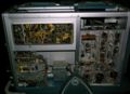
right internal view
-
top view of 4S1
-
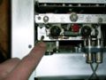
Coaxial interconnect from timing plug-in goes through the mainframe, into the 4S1, and ends here, at the sampler.
-
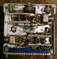
This is the sampler. The GaAs sampling diodes are arranged in a diamond shape and are directly connected to the socket from the delay line.
-
The delay line is a coil of coax going from the trigger pickoff to the sampler.
-
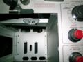
The 661 mainframe has two pieces of 50-ohm coax that connect the sampling unit bay to the timing unit bay. The plug-ins engage with these interconnects when inserted.
-
4S2 top view
-
4S2 front view


