7000 series readout system
For the 7000-series scopes, a system was required to display the instrument state such as input range, time/div etc. alongside or within the display. Earlier solutions had included fiber-optical/mechanical displays to the side of the CRT such as those in the 576 Curve Tracer.
The design ultimately selected for the 7000 series was proposed and designed by Barrie Gilbert. It uses the CRT beam to display annotations in the same focal plane as the scope's main display.
Layout

A total of eight display fields can be superimposed on the CRT picture, four on top and four at the bottom. These are logically associated with the four possible slots in full-size mainframes, with the top field corresponding to the first channel, primary timebase or primary function of a plug-in, and the bottom field corresponding to a second channel, delayed timebase, secondary function or unit label.
Mainframe circuit
The oscilloscope readout system produces a pulse train consisting of 10 successive negative-going pulses representing a possible character in a readout word, and is assigned a time-slot number corresponding to its position in the word. Each time-slot pulse is output at -15 V onto one of ten lines, labeled TS-1 through TS-10 (Time Slots 1 through 10), which are connected to the vertical and horizontal plug-in compartments.
Two output lines, row and column, are connected from each channel (two channels per plug-in compartment) back to the oscilloscope readout system. Data is encoded on these output lines as a pair of ten-level analog current sequences (in 100 μA steps from 0 to 1 mA), which can address a matrix of 10 × 10 positions. In this matrix, rows 1, 2, 4, 5 and 6 correspond to characters whereas others are used to encode instructions:

In time slot 1, special operations can be requested that affect the display in later time slots. These commands are designed to simplify display changes required by external probes that request beam identification or change input sensitivity. The "Identify" command switches to an internal program displaying IDENTIFY instead of any encoded value. Command R3/C1 requests an additional zero to be added starting in time slot 5, R3/C2 adds two such zeroes, R3/C3 shifts the selected prefix one code to the left (i.e. p → n, n → μ, μ → m, m → space), and R3/C4 shifts the prefix and adds a zero. (See the encoding circuit of the 7A18 plugin for an example implementation.) It is also possible to request a decimal point to be drawn without losing display digits, by encoding row 7 commmands in time slot 1.
The character generators are custom analog chips that provide X and Y output currents for ten characters of up to eight X/Y coordinate pairs inscribing each character. The in-character coordinate points are selected through an analog signal, not a digital code. The output values are generated by different emitter areas in integrated transistors.
Plugin circuit
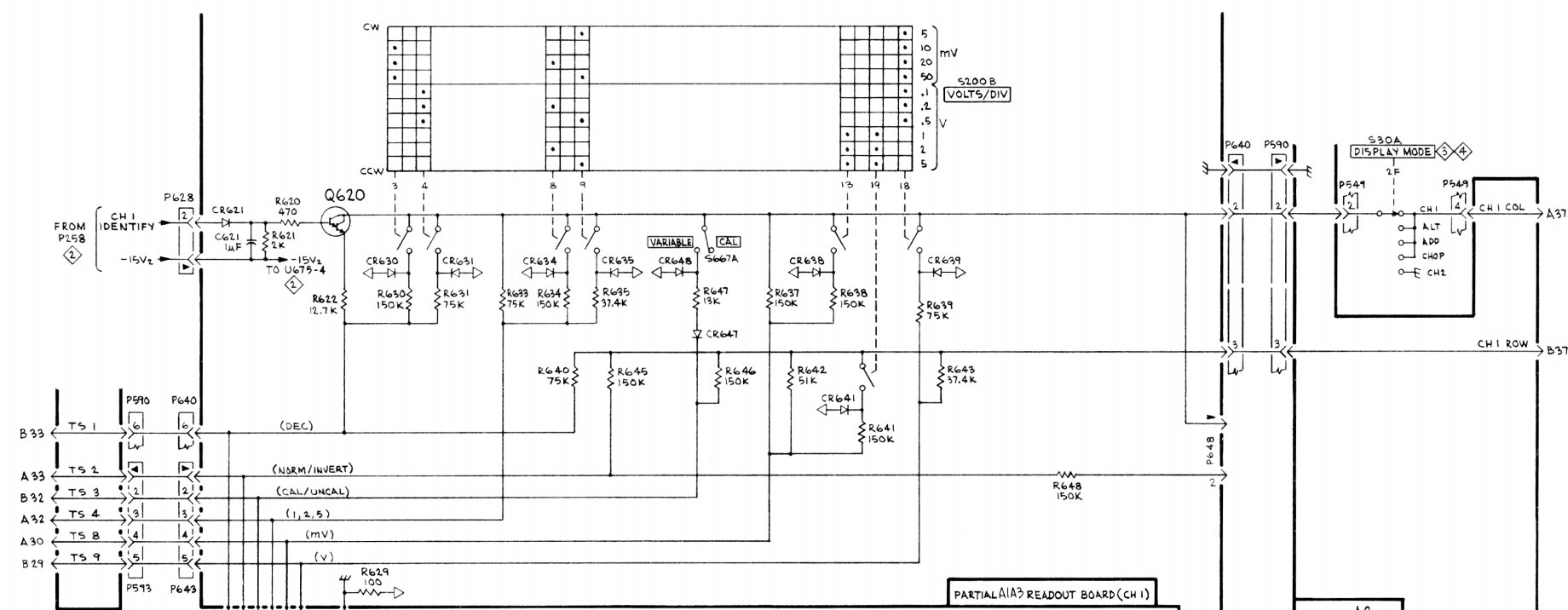
A plug-in encodes the desired read-out information either by connecting resistors between the output lines and the time-slot input lines, or by generating equivalent currents.
A simple plug-in such as a vertical amplifier will only require a small number of resistors and possibly diodes in addition to a suitably coded switch.
It will use TS1 to encode the number of zeros, TS2 to display a down-arrow indicating an inverted input, TS3 to display ">" or "<" if the input is uncalibrated, TS4 for a digit, TS8 for a unit prefix like "μ" and TS9 for a unit like "V". The other slots are unused:

Complex plugins
The 7M13 plugin allows the user to encode arbitrary text and numbers plus an optional picture counter value, for photographic documentation.
Digital delay or counter plugins like the 7D11 or 7D14 display up to 8 digit counts in the top field and a unit (e.g. MHz) in the bottom field.
The 067-0905-99 "Readout Exerciser" is a test fixture for the readout system.
Custom chips
- 155-0014-01 Analog to Decimal Converter
- 155-0015-01 Analog Data Switch
- 155-0017-00 Zero Logic Counter
- 155-0018-00 Zeros Logic
- 155-0019-00 Decimal Point and Spacing
- 155-0020-00 Output Assembler
- 155-0021-00 Timing Generator
- 155-0023-00 R-1 Character generator (Numerals 0 1 2 3 4 5 6 7 8 9)
- 155-0024-00 R-2 Character generator (Special Symbols ↓ < I / + - + C Δ >)
- 155-0025-00 R-4 Character generator (Prefixes m μ n p X K M G T R)
- 155-0026-00 R-5 Character generator (Letters S V A W H d B c Ω E)
- 155-0027-00 R-6 Character generator (Special Alpha U N L Z Y P F J Q D)
- 155-0038-01 D/A converter

Literature
- Barrie Gilbert, Monolithic Analog READ-ONLY Memory for Character Generation, IEEE J. of Solid-State Circuits, 1971.
Links
- Repair of readout and installation of readout board in another scope (many photos, German text)
Character code table
- A R5/C3
- B R5/C7
- C R2/C8
- D R6/C10
- E R5/C10
- F R6/C7
- G R4/C8
- H R5/C5
- I R2/C3
- J R6/C8
- K R4/C6
- L R6/C3
- M R4/C7
- N R6/C2
- P R6/C6
- Q R6/C9
- R R4/C10
- S R5/C1
- T R4/C9
- U R6/C1
- V R5/C2
- W R5/C4
- X R4/C5
- Y R6/C5
- Z R6/C4
- m R4/C1
- μ R4/C2
- n R4/C3
- p R4/C4
- d R5/C6
- c R5/C8
- 0 R1/C1
- 1 R1/C2
- 2 R1/C3
- 3 R1/C4
- 4 R1/C5
- 5 R1/C6
- 6 R1/C7
- 7 R1/C8
- 8 R1/C9
- 9 R1/C10
- ↓ R2/C1
- < R2/C2
- / R2/C4
- > R2/C10
- Δ R2/C9
- + R2/C5 or R2/C7
- – R2/C6
- Ω R5/C9