7704A: Difference between revisions
No edit summary |
No edit summary |
||
| Line 61: | Line 61: | ||
<gallery> | <gallery> | ||
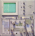
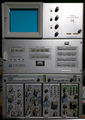
Tek 7704a trace.jpg | Tek 7704a trace.jpg | 7704A displaying a trace | ||
Tek 7704a 7a26 7b92a trace.jpg | 7704A displaying a trace | |||
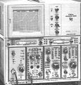
Tek 7704A 1.jpg | 7704A | Tek 7704A 1.jpg | 7704A | ||
USA Tektronix 7704A Front0.jpg | 7704A | USA Tektronix 7704A Front0.jpg | 7704A | ||
Revision as of 14:32, 29 September 2020

The Tektronix 7704A is a modular oscilloscope in the 7000 series that takes two 7000-series vertical plug-ins and two 7000-series horizontal plug-ins. Main designers were Luis Navarro (electrical) and Bob Shand (mechanical).
The 7704A followed the 7704 in 1972, improving bandwidth from 150 to 200 MHz (regular model, optimized for transient response) or 250 MHz (option 9, bandwidth-optimized). The R7704 rack-mount version continued to be named just R7704.
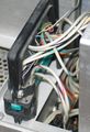
The 7704A has a special modular construction. At the bottom is the "A7704 acquisition unit", which contains the power supply, plug-in slots, and main interface board. On top is the "D7704 display unit", which contains the CRT, HV power supply, and output amplifiers for driving the deflection plates of the CRT. These units detach. A large multi-pin connector passes signals and power from the acquisition unit to the display unit. It is important not to damage this connector when assembling or disassembling the units.
An optional component, the P7001 Processing Unit, can be added to a 7704A between the acquisition unit and the display unit. The Acquisition Unit of the 7704A, the P7001 Processor, and the Display Unit of the 7704A are connected by the Acquisition-Processor-Display (APD) Interface shown below.
Key Specifications
| Fastest cal. sweep | 2 ns/Div |
|---|---|
| Bandwidth | 200 MHz (with 7A19) |
| Calibrator | 4 mV to 40 V in decade steps, 2/20/200/400 mV into 50 Ω, 40 mA; 1 kHz |
| Outputs | Vertical Signal Out (25 mV/Div, 60 MHz), +Sawtooth, +Gate, Cal, camera power, probe power |
| Acceleration voltage | 24 kV |
| Power | 90-132 V or 180-264 V, 48-440 Hz, 180 W max. |
| Weight | 13.6 kg (30 lbs) |
| Size | 34.5 cm × 30.5 cm × 57.7 cm (H×W×L) |
| Options |
|
Internals
The vertical amplifier in the 7704A uses the 155-0077-00 hybrid.
In the 7704A, the readout board is located behind a back panel carrying two LEMO S-series connectors for probe power. This placement was intended to allow easy retrofitting of a readout board into an Option 1 instrument, however, the readout board is not a plug-in card − several cables have to be attached to the board.
The 7704A SMPS uses a custom Tek chip (155-0067-02) to implement the control functions. For the initial start of the SMPS oscillator on power-up, early 7704As use a diac and later 7704As use a unijunction transistor in the starter circuit.
Links
- Luis Navarro, Bob Shand: The 7704A-Extended Performance Plus Modularity. In TekScope Vol. 4 No. 3, May 1972
- 7704A page at amplifier.cd (with repair report, German) / translated
- 7704A demo @ YouTube
Pictures
-
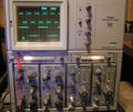
7704A displaying a trace
-
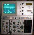
7704A displaying a trace
-
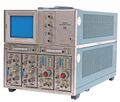
7704A
-
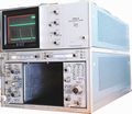
7704A
-
7704A + 7D01 (from advertisement)
-
7704A picture from manual
-
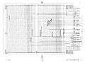
APD Interface
-
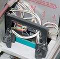
Interconnect plug in normal position
-
Interconnect plug on storage fixture
-
7704A with P7001
-
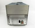
7704A rear
-
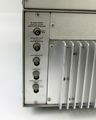
7704A rear
-
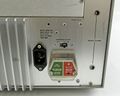
7704A rear
-
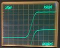
7704A Mod 9 rise time with 7A29 is 1.25 ns. Sweep was adjusted for exactly 1 ns / div using 1 GHz reference.


