7854: Difference between revisions
No edit summary |
No edit summary |
||
| (52 intermediate revisions by 9 users not shown) | |||
| Line 1: | Line 1: | ||
{{Oscilloscope Sidebar| | {{Oscilloscope Sidebar | ||
|manufacturer=Tektronix | |||
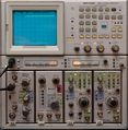
image=tek7854.jpg| | |series=7000-series scopes | ||
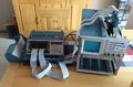
caption=Tektronix 7854 on a [[K213]] cart| | |model=7854 | ||
introduced=1980 | | |image=tek7854.jpg | ||
discontinued=1990 | | |caption=Tektronix 7854 on a [[K213]] cart | ||
summary=400 MHz waveform-processing scope| | |introduced=1980 | ||
manuals= | |discontinued=1990 | ||
* [ | |summary=400 MHz waveform-processing scope | ||
|designers=Tom Rousseau;Les Larson;Jack Collins;Ellen Deleganes;Jim Schlegel;Gary Fladstol;Val Garuts;Tim Holte;Burt Johnson;Bruce Kingsland;Wes Kosta;Jim Tallman;Kirk Wimmer | |||
* [[Media: | |manuals= | ||
* [ | * [[Media:070-2873-00.pdf | 7854 Operators Manual ]] | ||
* [[Media:070-2874-01.pdf | 7854 Service Manual, Sept. 1981 ]] | |||
* [[Media:Tektronix 7854 Manual Change Info D.pdf | 7854 Manual Change Information ]] through Jan 1991 | |||
* [[Media:7854 | * [[Media:Tektronix 7854 Test Point and Adjustment Locations D.pdf | 7854 Test Points and Adjustment Locations ]] | ||
* [[Media: | * [[Media:Tektronix 7854 Schematics D.pdf | 7854 Schematics ]] | ||
* [[Media: | |||
'''Modifications''' | |||
* [[Media:040-1066-00.pdf | 040-1066-00: Vertical Pickoff Amplifier Drift Improvement ]] (1982) | |||
* [[Media: | * [[Media:045-0056-00.pdf | 045-0056-00: Firmware update 1.03 ]] (1983) | ||
'''Troubleshooting''' | |||
* [[Media: | * [[Media:070-2875-00.pdf | 7854 Test Procedures using the 067-0911-00 & up Diagnostic Test Interface Volume 1 Service ]] | ||
* [[Media: | * [[Media:070-3887-00.pdf | 7854 Test Procedures using the 067-0911-00 & up Diagnostic Test Interface Volume 2 Service ]] | ||
* [[Media: | * [[Media:070-2876-00.pdf | 7854 Diagnostic Troubleshooting using the 067-0911-00 & up Diagnostic Test Interface ]] | ||
* [[Media: | * [[Media:070-2972-00.pdf | 7854 Signature Analysis Tables using 067-0911-00 ]] | ||
* [[Media:070-3801-00.pdf | 7854 Diagnostic Memory service manual ]] | |||
* [ | |||
'''Other Info''' | '''Other Info''' | ||
* [[Media:Tekniques 15Dec1980 vol4 no8 7854excerpt.pdf|7854-Related Excerpt from Tekniques Vol 4 No 8 | * [[Media:Tekniques 15Dec1980 vol4 no8 7854excerpt.pdf | 7854-Related Excerpt from Tekniques Vol 4 No 8 ]] | ||
* [[Media:Tek 7854 | * [[Media:Tek 7854 eis signature page.pdf | Tektronix 7854 Engineering Instrument Specification Signature Page ]] | ||
* [[Media:Tek_7854_42W5198_specs_orderinginfo.pdf | 7854 specifications and ordering information ]] | |||
* [[Media:7854 source 1v02 1982 cover.pdf | Tektronix 7854 Source Code ]] | |||
* [[Media:Tek 7854 wizard workshop.pdf | Tektronix Wizard Workshop Articles Relating to the 7854 ]] | |||
* [[Media:Tek 7854 factory analog calibration procedure.pdf | Tektronix 7854 Factory Analog Calibration Procedure ]] | |||
* [[Media:Tek 7854 factory digital calibration procedure.pdf | Tektronix 7854 Factory Digital Calibration Procedure ]] | |||
* [[Media:Tek 7854 board test procedures.pdf | Tektronix 7854 Board Test Procedures ]] | |||
* [[Media:Tek 7854 npi.pdf | Tektronix 7854 New Product Introduction Review ]] | |||
* [[Media:Dennis Tillman 7104-7854 SMPS Dummy Load.pdf | Dummy load for troubleshooting 7854 and 7104 SMPS (Dennis Tillman) ]] | |||
}} | }} | ||
The '''Tektronix 7854 Waveform Processing Oscilloscope''', introduced in 1980, is a 400 MHz combined analog / digital | The '''Tektronix 7854 Waveform Processing Oscilloscope''', introduced in 1980, is a 400 MHz combined analog / digital | ||
mainframe in the 7000 series that takes two vertical and two horizontal [[7000-series_plug-ins|7000-series plug-ins]]. | mainframe in the 7000 series that takes two vertical and two horizontal [[7000-series_plug-ins|7000-series plug-ins]]. | ||
In addition to a conventional analog (real time) scope, it contains an equivalent-time sampling 10-bit digitizer and a | In addition to a conventional analog (real time) scope, it contains an equivalent-time sampling 10-bit digitizer and a programmable waveform processor with GPIB interface. | ||
programmable waveform processor with GPIB interface. Single-shot, pretrigger acquisition is possible with special [[7B87]] time base using real-time sampling. | Single-shot, pretrigger acquisition is possible with the special [[7B87]] time base using real-time sampling. | ||
The project manager for the 7854 was [[Tom Rousseau]]. | The project manager for the 7854 was [[Tom Rousseau]]. | ||
During early development, before it was given the name "7854", the product was referred to as the "Smart Scope", | |||
and the digital processing was called the "smarts". | |||
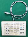
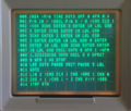
The waveform processor can be programmed using a detachable calculator-style keyboard, using postfix operators | The waveform processor can be programmed using a detachable calculator-style keyboard, using postfix operators ("[[wikipedia:Reverse Polish notation|reverse Polish notation]]" like [[wikipedia:HP-35|HP calculators]]) that operate on entire waveforms, not just individual numbers. | ||
("reverse Polish notation" like HP calculators) that operate on entire waveforms, not just individual numbers. | |||
{{BeginSpecs}} | {{BeginSpecs}} | ||
{{Spec | Bandwidth | (analog) 400 MHz }} | {{Spec | Bandwidth | (analog) 400 MHz }} | ||
{{Spec | Fastest cal. sweep | 500 ps }} | {{Spec | Fastest cal. sweep | 500 ps/Div }} | ||
{{Spec | Sample rate | 500 kHz (stores repetitive waveforms up to 400 MHz) }} | {{Spec | Sample rate | 500 kHz (stores repetitive waveforms up to 400 MHz) }} | ||
{{Spec | Resolution | 10 bit }} | {{Spec | Resolution | 10 bit }} | ||
{{Spec | Acquisition depth | 128, 256, 512 or 1024 points }} | {{Spec | Acquisition depth | 128, 256, 512 or 1024 points }} | ||
{{Spec | Memory capacity | 2048 waveform points in up to 16 waveforms (optional expansion to 5120 points and 40 waveforms) }} | {{Spec | Memory capacity | 2048 waveform points in up to 16 waveforms (optional expansion to 5120 points and 40 waveforms) }} | ||
{{Spec | Single shot | events and pretrigger up to 50 µs/div ("2.5 µs/point") with the [[7B87]] Time Base}} | {{Spec | Single shot | events and pretrigger up to 50 µs/div ("2.5 µs/point") with the [[7B87]] Time Base}} | ||
{{Spec | CRT | [[154-0644-05]] ([[Phosphor| | {{Spec | CRT | [[154-0644-05]] ([[Phosphor|P31]]) or [[154-0893-09]] ([[Phosphor|P11]]); cathode −3 kV, anode +21 kV, [[distributed deflection plates|distributed vertical deflection plates]] }} | ||
{{Spec | Features | | {{Spec | Features | | ||
* Signal | * Signal averaging | ||
* Cursor measurements | * Cursor measurements | ||
* Waveform parameter measurements | * Waveform parameter measurements | ||
* GPIB | * GPIB interface (standard) | ||
* Waveform calculation operators - add, multiply, square root, log, abs | * Waveform calculation operators - add, multiply, square root, log, abs | ||
* Internal RPN programming language (Reverse Polish Notation) | * Internal RPN programming language (Reverse Polish Notation) | ||
* Keystroke | * Keystroke programming (up to 2000 keystrokes with option 2D) | ||
* | * Programmable text display on screen | ||
}} | |||
{{Spec | Options | | |||
* Option 02: X-Y Phase Correction | |||
* Option 03: EMC Modification | |||
* Option 78: P11 Phosphor | |||
* Option 2D: 4K Expanded memory storage for up to 40 waveforms and 2000 keystrokes | |||
}} | }} | ||
{{Spec | Power consumption | 230 W }} | |||
{{Spec | Weight | 42 lbs / 19 kg }} | |||
{{EndSpecs}} | {{EndSpecs}} | ||
== | ==Documents== | ||
{{Documents|Link=7854}} | |||
= | |||
==Prices== | ==Prices== | ||
| Line 83: | Line 86: | ||
! Year | ! Year | ||
! 1981 | ! 1981 | ||
! 1984 | |||
! 1990 | ! 1990 | ||
|- | |- | ||
! Catalog price | ! Catalog price | ||
| $10,500 | | $10,500 | ||
| $14,230 | |||
| $17,000 | | $17,000 | ||
|- | |- | ||
! | ! In 2023 Dollars | ||
| $ | | $35,500 | ||
| $ | | $42,000 | ||
| $39,900 | |||
|} | |} | ||
| Line 103: | Line 109: | ||
* [[067-0914-00]] Extender Board 80-Pin (used with the A27-MPU and A28-RAM Boards) | * [[067-0914-00]] Extender Board 80-Pin (used with the A27-MPU and A28-RAM Boards) | ||
* [[067-0915-00]] Extender Board 124-Pin (used with the A26-Control Logic and A29-Display Boards) | * [[067-0915-00]] Extender Board 124-Pin (used with the A26-Control Logic and A29-Display Boards) | ||
==Software== | |||
* [[Media:42W-5802.pdf|Application Note 42W-5802, BASIC Software Programs for Communicating Between the 7854 and IBM PC]], 1985 (OCR) | |||
* [[Media:Tek_7854_sw.zip|7854 software in BASIC]] | |||
* [[Media:Fftprog.zip | FFT program]] | |||
==Links== | ==Links== | ||
* [[Media:Tek 7854 design team.pdf|Tek 7854 Design Team]] | * ''[[Media:Handshake winter 1980 1981.pdf|Talking to the 7854 Oscilloscope with TEK SPS BASIC]]'' in ''Handshake'', Winter 1980/81 | ||
* [ | * [[Media:Tek 7854 design team.pdf|Tek 7854 Design Team]] Note: The graduation cap on the Engineering Release cake (page 8) signifies that it is the "Smart Scope". | ||
* [ | * [https://www.curiousmarc.com/instruments/tek-7854-oscilloscope Tek 7854 @ curiousmarc] (with links to videos) | ||
* [https://amplifier.cd/Test_Equipment/Tektronix/Tektronix_7000_series_mainframe/7854.html Tek 7854 @ amplifier.cd] | |||
* [https://groups.io/g/TekScopes/topic/7854_roms_the_whole_story/73320555 7854 ROMs, the whole story] @ TekScopes groups.io | |||
* [https://vintagetek.org/7854-mostek-mkb36000-rom-repairs Mostek ROM Repairs @ vintagetek.org] | * [https://vintagetek.org/7854-mostek-mkb36000-rom-repairs Mostek ROM Repairs @ vintagetek.org] | ||
* [https://paulcarbone.com/blog/tektronix-7854/ overview of ROM repair options @ paulcarbone.com] | * [https://paulcarbone.com/blog/tektronix-7854/ overview of ROM repair options @ paulcarbone.com] | ||
==Internals== | |||
The acquisition system uses what Tektronix termed a "display-oriented random sampling digitizing technique". | |||
It simultaneously digitizes a pair of X and Y signal values at a rate of 3.5 µs/point, using sample/hold circuits based on Schottky diode bridges, and a single 10-bit successive-approximation ADC. The Y sample value is then written into the memory location addressed by the X value, using DMA (direct memory access, i.e. bypassing the CPU). | |||
The CPU in the 7854 is a [[Texas Instruments TMS9900]] 16-bit microprocessor, known from the infamous TI-99/4 home computer of the late 70s, with 32+6KByte ROM and 8KByte RAM. | |||
The firmware consists of mask ROMs, an FPLA, and patch EPROMs. These ROMs (particularly the early ones from Mostek) are a common point-of-failure. Several remedies exist, see the [[7854/Repairs|Repairs]] page. | |||
==Pictures== | ==Pictures== | ||
| Line 115: | Line 137: | ||
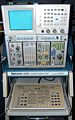
tek7854-with-keyboard.jpg|Tektronix 7854 with Waveform Calculator keyboard, [[7A26]], [[7M13]], [[7D15]], [[7B87]] | tek7854-with-keyboard.jpg|Tektronix 7854 with Waveform Calculator keyboard, [[7A26]], [[7M13]], [[7D15]], [[7B87]] | ||
Tek 7854 e1.jpg|7854 Front with [[7A26]],[[7B85]],[[7B87]] | Tek 7854 e1.jpg|7854 Front with [[7A26]],[[7B85]],[[7B87]] | ||
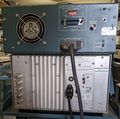
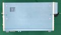
Tek 7854 rear.jpg|7854 Rear | Tek 7854 e5.jpg|7854 Rear, older version | ||
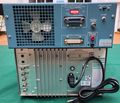
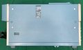
7854-rear.jpg|7854 Rear | Tek 7854 rear.jpg|7854 Rear, older version, separate RAM and ROM boards, external battery backup, old-style, silent fan | ||
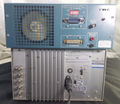
7854-rear.jpg|7854 Rear, newer version, combined RAM and ROM boards, internal battery backup, new-style, less silent fan | |||
Tek 7854 e2.jpg|7854 Top | |||
Tek 7854 e3.jpg|7854 Left | |||
Tek 7854 e4.jpg|7854 Right | |||
Tek_7854_keyboard.jpg|Waveform Calculator Keyboard | Tek_7854_keyboard.jpg|Waveform Calculator Keyboard | ||
Tek 7854 e6.jpg|Waveform Calculator Keyboard | Tek 7854 e6.jpg|Waveform Calculator Keyboard | ||
7854 keyboard inside.jpg|inside the Waveform Calculator Keyboard | |||
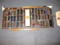
Tek7854 digital boards.jpg | Digital section in the 7854 | Tek7854 digital boards.jpg | Digital section in the 7854 | ||
Tek 7854 a2.jpg|A2 Mode Switch | Tek 7854 a2.jpg|A2 Mode Switch | ||
Tek 7854 mode switch.jpg|A2 Mode Switch | Tek 7854 mode switch.jpg|A2 Mode Switch | ||
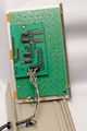
Tek 7854 aux reg.jpg|A7 | Tek_7854_AUX_REG-A7.jpg|The A7 / Auxiliary regulator | ||
Tek 7854 aux reg.jpg|A different revision of the A7 board | |||
Tek 7854 main interface.jpg|A11 Main Interface | Tek 7854 main interface.jpg|A11 Main Interface | ||
Tek 7854 a15b.jpg|A15 Signal Output | Tek 7854 a15b.jpg|A15 Signal Output | ||
| Line 134: | Line 162: | ||
Tek 7854 t1.jpg|A21 Z-Axis | Tek 7854 t1.jpg|A21 Z-Axis | ||
Tek 7854 digitizer.jpg|A25 Digitizer | Tek 7854 digitizer.jpg|A25 Digitizer | ||
Tek 7854 a26.jpg |A26 Control Logic Board | Tek_7854_CONTROL_LOGIC-A26.jpg| A26 Control Logic Board | ||
Tek 7854 a26.jpg |A26 Control Logic Board | |||
Tek 7854 logic.jpg|A26 Control Logic Board | Tek 7854 logic.jpg|A26 Control Logic Board | ||
Tek 7854 mpu.jpg|A27 | Tek_7854_MPU-A27.jpg|A27 MPU | ||
Tek 7854 mpu.jpg|A different revision of the A27 board | |||
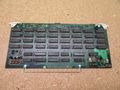
Tek 7854 ram expansion.jpg|A28 RAM Board | Tek 7854 ram expansion.jpg|A28 RAM Board | ||
Tek 7854 a28.jpg|A28 RAM Board with option 2D (RAM Expansion) | Tek 7854 a28.jpg|A28 RAM Board with option 2D (RAM Expansion) | ||
A29.jpg|A29 Display Board | A29.jpg|A29 Display Board | ||
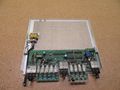
Tek 7854 gpib.jpg|A30 GPIB | Tek_7854_GPIB-A30.jpg|A30 / GPIB board | ||
Tek 7854 gpib.jpg|A30 GPIB, different revision | |||
A31.jpg|A31 ROM Board | A31.jpg|A31 ROM Board | ||
Tek 7854 a32.jpg|A32 Rear Panel Connector | Tek 7854 a32.jpg|A32 Rear Panel Connector | ||
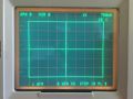
Tek 7854 trace1.jpg | Tek 7854 trace1.jpg | ||
Tek 7854 trace2.jpg | Tek 7854 trace2.jpg | ||
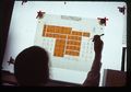
Tek_7854_development_1978.jpg|Picture of 7854 during development. Note the different measurement keyboard layout. Picture might date from late 1978 | Tek_7854_development_1978.jpg|Picture of 7854 during development. Note the different measurement keyboard layout. Picture might date from late 1978 | ||
Tek_7854_development_sept_1978.jpg|Picture of designing the 7854 waveform calculator keyboard. note the different Keyboard layout. | Tek_7854_development_sept_1978.jpg|Picture of designing the 7854 waveform calculator keyboard. note the different Keyboard layout. | ||
7854_Alignment.jpg | Alignment Pattern | 7854_Alignment.jpg | Alignment Pattern | ||
7854_pattern_program.png | Program for generating Alignment Pattern | 7854_pattern_program.png | Program for generating Alignment Pattern | ||
Tek_7854_rise_time.jpg | Mainframe rise time measured with [[067-0587-02]] | |||
Tek_microlab_connected_7854_01.jpg|7854 diagnostics system with [[MicroLab I]] | |||
</gallery> | </gallery> | ||
==Memory Maps== | |||
===Devices with separated ROM and RAM boards (SN < B100000)=== | |||
{| class="wikitable" | |||
|- | |||
! Address Range | |||
! Size | |||
! ICs | |||
! colspan="3"|Purpose | |||
|- | |||
|align="center"| 0000...3FFE | |||
|align="center"| 8k | |||
|align="center"| U100, U110 | |||
|align="center" colspan="3"|ROM | |||
|- | |||
|align="center"| 4000...7FFE | |||
|align="center"| 8k | |||
|align="center"| U200, U210 | |||
|align="center" colspan="3"|ROM | |||
|- | |||
|align="center"| 8000...8FFE | |||
|align="center"| 2k | |||
|align="center"| U300, U310 | |||
|align="center" colspan="3"|PATCH ROM “for future use” | |||
|- | |||
|align="center"| 9000...9FFE | |||
|align="center"| 2k | |||
|align="center"| U400,U410 | |||
|align="center" colspan="3"|PATCH + ROM | |||
|- | |||
! | |||
! | |||
! | |||
! 2k RAM | |||
! 4k RAM | |||
! 8k RAM | |||
|- | |||
|align="center"| A000...A7FE | |||
|align="center"| 1k | |||
|align="center"| U510,U520,U530,U540 | |||
|align="center"| x | |||
|align="center"| x | |||
! x | |||
|- | |||
|align="center"| A800...AFFE | |||
|align="center"| 1k | |||
|align="center"| U610,U620,U630,U640 | |||
|align="center"| | |||
|align="center"| x | |||
|align="center"| x | |||
|- | |||
|align="center"| B000...B7FE | |||
|align="center"| 1k | |||
|align="center"| U710,U720,U730,U740 | |||
|align="center"| | |||
|align="center"| | |||
|align="center"| x | |||
|- | |||
|align="center"| B800...BFFE | |||
|align="center"| 1k | |||
|align="center"| U810,U820,U830,U840 | |||
|align="center"| | |||
|align="center"| | |||
|align="center"| x | |||
|- | |||
|align="center"| C000...C7FE | |||
|align="center"| 1k | |||
|align="center"| U110,U120,U130,U140 | |||
|align="center"| | |||
|align="center"| | |||
|align="center"| x | |||
|- | |||
|align="center"| C800...CFFE | |||
|align="center"| 1k | |||
|align="center"| U210,U220,U230,U240 | |||
|align="center"| | |||
|align="center"| | |||
|align="center"| x | |||
|- | |||
|align="center"| D000...D7FE | |||
|align="center"| 1k | |||
|align="center"| U310,U320,U330,U340 | |||
|align="center"| | |||
|align="center"| x | |||
|align="center"| x | |||
|- | |||
|align="center"| D800...DFFE | |||
|align="center"| 1k | |||
|align="center"| U410,U420,U430,U440 | |||
|align="center"| x | |||
|align="center"| x | |||
|align="center"| x | |||
|- | |||
|align="center"| E000...E37E | |||
|align="center"| | |||
|align="center"| | |||
|align="center" colspan="3"|GPIB, Keyboards, Digitizer,... | |||
|- | |||
|align="center"| E380...FFFE | |||
|align="center"| | |||
|align="center"| | |||
|align="center" colspan="3"|Reserved for Diagnostic Interface | |||
|} | |||
===Devices with combined RAM+ROM Board (SN >= B100000)=== | |||
{| class="wikitable" | |||
|- | |||
! Address Range | |||
! Size | |||
! ICs | |||
! Purpose | |||
|- | |||
|align="center"| 0000...7FFE | |||
|align="center"| 16k | |||
|align="center"| U220,U320 | |||
|align="center"| ROM | |||
|- | |||
|align="center"| 8000...9FFE | |||
|align="center"| 4k | |||
|align="center"| U200,U300 | |||
|align="center"| ROM for future use | |||
|- | |||
|align="center"| A000...DFFE | |||
|align="center"| 8k | |||
|align="center"| U400,U410 | |||
|align="center"| RAM | |||
|- | |||
|align="center"| E000...E37E | |||
|align="center"| 4k | |||
|align="center"| | |||
|align="center"| GPIB, Keyboards, Digitizer,... | |||
|- | |||
|align="center"| E380...FFFE | |||
|align="center"| | |||
|align="center"| | |||
|align="center"| Reserved for Diagnostic Interface | |||
|} | |||
===Devices with installed Diagnostic Boards (all serial numbers)=== | |||
{| class="wikitable" | |||
|- | |||
! Address Range | |||
! Size | |||
! ICs | |||
! Purpose | |||
|- | |||
|align="center"| 0000...0FFE | |||
|align="center"| 2k | |||
|align="center"| U430,U330 | |||
|align="center"| ROM | |||
|- | |||
|align="center"| 1000...1FFE | |||
|align="center"| 2k | |||
|align="center"| U410,U310 | |||
|align="center"| ROM | |||
|- | |||
|align="center"| 2000...2FFE | |||
|align="center"| 2k | |||
|align="center"| U200,U100 | |||
|align="center"| ROM | |||
|- | |||
|align="center"| 3000...3FFE | |||
|align="center"| 2k | |||
|align="center"| U220,U120 | |||
|align="center"| ROM | |||
|- | |||
|align="center"| 4000...4FFE | |||
|align="center"| 2k | |||
|align="center"| U420,U320 | |||
|align="center"| ROM | |||
|- | |||
|align="center"| 5000...5FFE | |||
|align="center"| 2k | |||
|align="center"| U400,U300 | |||
|align="center"| ROM | |||
|- | |||
|align="center"| 6000...6FFE | |||
|align="center"| 2K | |||
|align="center"| U210,U110 | |||
|align="center"| ROM | |||
|- | |||
|align="center"| 7000...7FFE | |||
|align="center"| 2K | |||
|align="center"| | |||
|align="center"| ROM for future use | |||
|- | |||
|align="center"| 8000...7FFE | |||
|align="center"| 4k | |||
|align="center"| | |||
|align="center"| Not used | |||
|- | |||
|align="center"| 9800...9FFE | |||
|align="center"| | |||
|align="center"| | |||
|align="center"| RAM in Microlab I, disabled when standard ROM is in 7854 | |||
|- | |||
|align="center"| A000...DFFE | |||
|align="center"| 2...8k | |||
|align="center"| | |||
|align="center"| RAM – see tables above | |||
|- | |||
|align="center"| E000...E37E | |||
|align="center"| | |||
|align="center"| | |||
|align="center"| GPIB, Keyboards, Digitizer,... | |||
|- | |||
|align="center"| E380...E39E | |||
|align="center"| | |||
|align="center"| | |||
|align="center"| BKREGCS Breakpoint address register chip select | |||
|- | |||
|align="center"| E3A0...E3BE | |||
|align="center"| | |||
|align="center"| | |||
|align="center"| CTREGCS control register chip select | |||
|- | |||
|align="center"| E3C0...E3DE | |||
|align="center"| | |||
|align="center"| | |||
|align="center"| BKDATA breakpoint data latch | |||
|- | |||
|align="center"| E3E0 | |||
|align="center"| | |||
|align="center"| | |||
|align="center"| F/P Display Data | |||
|- | |||
|align="center"| E3E2 | |||
|align="center"| | |||
|align="center"| | |||
|align="center"| F/P Display Data | |||
|- | |||
|align="center"| E3E4 | |||
|align="center"| | |||
|align="center"| | |||
|align="center"| F/P Keyboard Data | |||
|- | |||
|align="center"| E3E6 | |||
|align="center"| | |||
|align="center"| | |||
|align="center"| F/P Keyboard flag reset | |||
|- | |||
|align="center"| E3E8 | |||
|align="center"| | |||
|align="center"| | |||
|align="center"| Terminal I/O Control | |||
|- | |||
|align="center"| E3EA | |||
|align="center"| | |||
|align="center"| | |||
|align="center"| Terminal I/O Data | |||
|- | |||
|align="center"| E3EC | |||
|align="center"| | |||
|align="center"| | |||
|align="center"| Cassette I/O Control | |||
|- | |||
|align="center"| E3EE | |||
|align="center"| | |||
|align="center"| | |||
|align="center"| Cassette I/O Data | |||
|- | |||
|align="center"| E3F0 | |||
|align="center"| | |||
|align="center"| | |||
|align="center"| Modem I/O Control | |||
|- | |||
|align="center"| E3F2 | |||
|align="center"| | |||
|align="center"| | |||
|align="center"| Modem I/O Data | |||
|- | |||
|align="center"| E3F4...E3FE | |||
|align="center"| | |||
|align="center"| | |||
|align="center"| ONBDIO on board input/output to microlab I | |||
|- | |||
|align="center"| E400...E7FE | |||
|align="center"| | |||
|align="center"| | |||
|align="center"| RAM in Microlab I | |||
|- | |||
|align="center"| E800...EFFE | |||
|align="center"| | |||
|align="center"| U120,U225 | |||
|align="center"| ROM - bank switched by PROMBK | |||
|- | |||
|align="center"| F000...FFFE | |||
|align="center"| | |||
|align="center"| U220,U320 | |||
|align="center"| ROM - bank switched by PROMBK | |||
|} | |||
==Components== | |||
{{Parts|7854}} | |||
[[Category:7000 series non-storage mainframes]] | [[Category:7000 series non-storage mainframes]] | ||
Latest revision as of 11:01, 29 January 2024

The Tektronix 7854 Waveform Processing Oscilloscope, introduced in 1980, is a 400 MHz combined analog / digital mainframe in the 7000 series that takes two vertical and two horizontal 7000-series plug-ins. In addition to a conventional analog (real time) scope, it contains an equivalent-time sampling 10-bit digitizer and a programmable waveform processor with GPIB interface. Single-shot, pretrigger acquisition is possible with the special 7B87 time base using real-time sampling. The project manager for the 7854 was Tom Rousseau. During early development, before it was given the name "7854", the product was referred to as the "Smart Scope", and the digital processing was called the "smarts".
The waveform processor can be programmed using a detachable calculator-style keyboard, using postfix operators ("reverse Polish notation" like HP calculators) that operate on entire waveforms, not just individual numbers.
Key Specifications
| Bandwidth | (analog) 400 MHz |
|---|---|
| Fastest cal. sweep | 500 ps/Div |
| Sample rate | 500 kHz (stores repetitive waveforms up to 400 MHz) |
| Resolution | 10 bit |
| Acquisition depth | 128, 256, 512 or 1024 points |
| Memory capacity | 2048 waveform points in up to 16 waveforms (optional expansion to 5120 points and 40 waveforms) |
| Single shot | events and pretrigger up to 50 µs/div ("2.5 µs/point") with the 7B87 Time Base |
| CRT | 154-0644-05 (P31) or 154-0893-09 (P11); cathode −3 kV, anode +21 kV, distributed vertical deflection plates |
| Features |
|
| Options |
|
| Power consumption | 230 W |
| Weight | 42 lbs / 19 kg |
Documents
Documents Referencing 7854
| Document | Class | Title | Authors | Year | Links |
|---|---|---|---|---|---|
| AX-4382.pdf | Application Note | WP1310 Waveform Processing System | 1980 | 7854 | |
| AX-4425.pdf | Application Note | WP1310 Signal Processing System | 1980 | 7854 • 4052 • WP1310 | |
| AX-4440.pdf | Application Note | 7854 On-board Digital Processing Refines Scope Measurements | Val Garuts • Jim Tallman | 1980 | 7854 |
| Tek 7854-AN-SPSBasic.pdf | Article | Talking to the 7854 scope with TEK SPS BASIC. | Bob Ramirez | 1980 | 7854 |
| Tekscope 1980 V12 N2.pdf | Article | New Products | 1980 | 7854 • 468 • AA501 • SG505 • CG551AP • 1900 • 7612D | |
| Tekscope 1980 V12 N3.pdf | Article | Digital Waveform Processing in a High-Performance 7000-Series Oscilloscope | Tom Rousseau • Bill Cox | 1980 | 7854 |
| 42AX-4682.pdf | Application Note | Introduction to 7854 Oscilloscope Measurement and Programming Techniques | 1981 | 7854 | |
| 7854 Application Programs.pdf | Application Note | 7854 Application Programs | Mike Mraz • Gary Kirchberger • Clark Foley • Roger Loop | 1981 | 7854 |
| AX-4281.pdf | Application Note | Measurement Variety. An Engineering Challenge Featuring the 7854 | 1981 | 7854 | |
| AX-4864.pdf | Application Note | 7854 Waveform Calculator Keyboard Guide | 1981 | 7854 | |
| 42W-4416-1.pdf | Application Note | Using the 7854 in a GPIB configuration | 1982 | 7854 • GPIB | |
| 42W-5334.pdf | Application Note | Automated TDR Testing Made Easy with the 7854 Oscilloscope/7S12 Sampler Plug-In | 1983 | 7854 • 7S12 | |
| 42W-5700.pdf | Application Note | Power Supply/Device Testing | 1984 | 7854 | |
| 42W-5802.pdf | Application Note | Basic software programs for communicating between the 7854 and IBM PC | 1985 | 7854 | |
| 42W-6732.pdf | Application Note | TekMAP 7854 Time and Amplitude Measurement Software | 1987 | 7854 | |
| 42W-6767.pdf | Application Note | Tektronix 7854TDR and 7854MPS measurement packages | 1987 | 7854 |
Prices
| Year | 1981 | 1984 | 1990 |
|---|---|---|---|
| Catalog price | $10,500 | $14,230 | $17,000 |
| In 2023 Dollars | $35,500 | $42,000 | $39,900 |
Diagnostic Test Interfaces
- 067-0911-00 Diagnostic Test Interface
- 067-0912-00 Analog Test Card for 7854
- 067-0961-00 Diagnostic Memory Board
Extender Boards
- 067-0913-00 Extender Board 44-Pin (used with the A30-GPIB and A31-ROM Boards)
- 067-0914-00 Extender Board 80-Pin (used with the A27-MPU and A28-RAM Boards)
- 067-0915-00 Extender Board 124-Pin (used with the A26-Control Logic and A29-Display Boards)
Software
- Application Note 42W-5802, BASIC Software Programs for Communicating Between the 7854 and IBM PC, 1985 (OCR)
- 7854 software in BASIC
- FFT program
Links
- Talking to the 7854 Oscilloscope with TEK SPS BASIC in Handshake, Winter 1980/81
- Tek 7854 Design Team Note: The graduation cap on the Engineering Release cake (page 8) signifies that it is the "Smart Scope".
- Tek 7854 @ curiousmarc (with links to videos)
- Tek 7854 @ amplifier.cd
- 7854 ROMs, the whole story @ TekScopes groups.io
- Mostek ROM Repairs @ vintagetek.org
- overview of ROM repair options @ paulcarbone.com
Internals
The acquisition system uses what Tektronix termed a "display-oriented random sampling digitizing technique".
It simultaneously digitizes a pair of X and Y signal values at a rate of 3.5 µs/point, using sample/hold circuits based on Schottky diode bridges, and a single 10-bit successive-approximation ADC. The Y sample value is then written into the memory location addressed by the X value, using DMA (direct memory access, i.e. bypassing the CPU).
The CPU in the 7854 is a Texas Instruments TMS9900 16-bit microprocessor, known from the infamous TI-99/4 home computer of the late 70s, with 32+6KByte ROM and 8KByte RAM.
The firmware consists of mask ROMs, an FPLA, and patch EPROMs. These ROMs (particularly the early ones from Mostek) are a common point-of-failure. Several remedies exist, see the Repairs page.
Pictures
-
-

-
7854 Rear, older version
-
7854 Rear, older version, separate RAM and ROM boards, external battery backup, old-style, silent fan
-
7854 Rear, newer version, combined RAM and ROM boards, internal battery backup, new-style, less silent fan
-
7854 Top
-
7854 Left
-
7854 Right
-
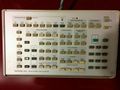
Waveform Calculator Keyboard
-
Waveform Calculator Keyboard
-
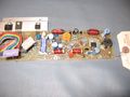
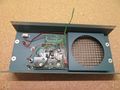
inside the Waveform Calculator Keyboard
-
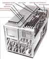
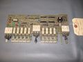
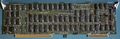
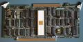
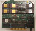
Digital section in the 7854
-
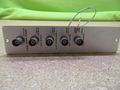
A2 Mode Switch
-
A2 Mode Switch
-

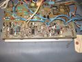
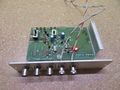
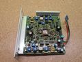
The A7 / Auxiliary regulator
-
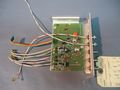
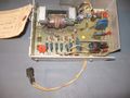
A different revision of the A7 board
-
A11 Main Interface
-
A15 Signal Output
-
A15 Signal Output
-
A15 Signal Out Board
-

A17 Horizontal Amp Board
-
A18 Vertical Amp Board
-
A19 Vertical Channel Switch
-
A19 Vertical Channel Switch
-
A20 High Voltage
-
A21 Z-Axis
-
A25 Digitizer
-
A26 Control Logic Board
-
A26 Control Logic Board
-
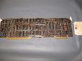
A26 Control Logic Board
-
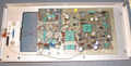
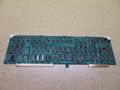
A27 MPU
-
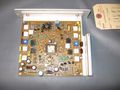
A different revision of the A27 board
-

A28 RAM Board
-
A28 RAM Board with option 2D (RAM Expansion)
-
A29 Display Board
-
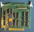
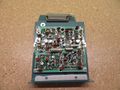
A30 / GPIB board
-
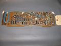
A30 GPIB, different revision
-
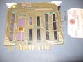
A31 ROM Board
-
A32 Rear Panel Connector
-

-

-
Picture of 7854 during development. Note the different measurement keyboard layout. Picture might date from late 1978
-
Picture of designing the 7854 waveform calculator keyboard. note the different Keyboard layout.
-
Alignment Pattern
-
Program for generating Alignment Pattern
-
Mainframe rise time measured with 067-0587-02
-
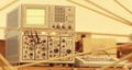
7854 diagnostics system with MicroLab I


Memory Maps
Devices with separated ROM and RAM boards (SN < B100000)
| Address Range | Size | ICs | Purpose | ||
|---|---|---|---|---|---|
| 0000...3FFE | 8k | U100, U110 | ROM | ||
| 4000...7FFE | 8k | U200, U210 | ROM | ||
| 8000...8FFE | 2k | U300, U310 | PATCH ROM “for future use” | ||
| 9000...9FFE | 2k | U400,U410 | PATCH + ROM | ||
| 2k RAM | 4k RAM | 8k RAM | |||
| A000...A7FE | 1k | U510,U520,U530,U540 | x | x | x |
| A800...AFFE | 1k | U610,U620,U630,U640 | x | x | |
| B000...B7FE | 1k | U710,U720,U730,U740 | x | ||
| B800...BFFE | 1k | U810,U820,U830,U840 | x | ||
| C000...C7FE | 1k | U110,U120,U130,U140 | x | ||
| C800...CFFE | 1k | U210,U220,U230,U240 | x | ||
| D000...D7FE | 1k | U310,U320,U330,U340 | x | x | |
| D800...DFFE | 1k | U410,U420,U430,U440 | x | x | x |
| E000...E37E | GPIB, Keyboards, Digitizer,... | ||||
| E380...FFFE | Reserved for Diagnostic Interface | ||||
Devices with combined RAM+ROM Board (SN >= B100000)
| Address Range | Size | ICs | Purpose |
|---|---|---|---|
| 0000...7FFE | 16k | U220,U320 | ROM |
| 8000...9FFE | 4k | U200,U300 | ROM for future use |
| A000...DFFE | 8k | U400,U410 | RAM |
| E000...E37E | 4k | GPIB, Keyboards, Digitizer,... | |
| E380...FFFE | Reserved for Diagnostic Interface |
Devices with installed Diagnostic Boards (all serial numbers)
| Address Range | Size | ICs | Purpose |
|---|---|---|---|
| 0000...0FFE | 2k | U430,U330 | ROM |
| 1000...1FFE | 2k | U410,U310 | ROM |
| 2000...2FFE | 2k | U200,U100 | ROM |
| 3000...3FFE | 2k | U220,U120 | ROM |
| 4000...4FFE | 2k | U420,U320 | ROM |
| 5000...5FFE | 2k | U400,U300 | ROM |
| 6000...6FFE | 2K | U210,U110 | ROM |
| 7000...7FFE | 2K | ROM for future use | |
| 8000...7FFE | 4k | Not used | |
| 9800...9FFE | RAM in Microlab I, disabled when standard ROM is in 7854 | ||
| A000...DFFE | 2...8k | RAM – see tables above | |
| E000...E37E | GPIB, Keyboards, Digitizer,... | ||
| E380...E39E | BKREGCS Breakpoint address register chip select | ||
| E3A0...E3BE | CTREGCS control register chip select | ||
| E3C0...E3DE | BKDATA breakpoint data latch | ||
| E3E0 | F/P Display Data | ||
| E3E2 | F/P Display Data | ||
| E3E4 | F/P Keyboard Data | ||
| E3E6 | F/P Keyboard flag reset | ||
| E3E8 | Terminal I/O Control | ||
| E3EA | Terminal I/O Data | ||
| E3EC | Cassette I/O Control | ||
| E3EE | Cassette I/O Data | ||
| E3F0 | Modem I/O Control | ||
| E3F2 | Modem I/O Data | ||
| E3F4...E3FE | ONBDIO on board input/output to microlab I | ||
| E400...E7FE | RAM in Microlab I | ||
| E800...EFFE | U120,U225 | ROM - bank switched by PROMBK | |
| F000...FFFE | U220,U320 | ROM - bank switched by PROMBK |
Components
Some Parts Used in the 7854
| Part | Part Number(s) | Class | Description | Used in |
|---|---|---|---|---|
| 154-0644-00 | 154-0644-00 • 154-0644-04 • 154-0644-05 • 154-0644-09 | CRT | CRT with distributed deflection plates | 7704A • 7854 • 7904 • 7904A • R7903 |
| 155-0009-00 | 155-0009-00 | Monolithic integrated circuit | horizontal lockout logic | 7504 • 7514 • 7704 • 7704A • R7704 • 7834 • 7844 • 7854 • 7904 • R7903 • 7904A • 7934 • 7104 |
| 155-0010-00 | 155-0010-00 | Monolithic integrated circuit | chop divider and blanking | 7504 • 7514 • 7704 • R7704 • 7704A • 7834 • 7854 • 7904 • R7903 • 7904A • 7934 • 7104 |
| 155-0011-00 | 155-0011-00 | Monolithic integrated circuit | clock and chop blanking | 485 • 7313 • 7403N • R7403N • 7503 • 7504 • 7514 • 7603 • AN/USM-281C • 7613 • 7623 • 7623A • 7633 • 7704 • R7704 • 7704A • 7834 • 7844 • 7854 • 7904 • 7904A • R7903 • R7912 • 7912AD • 7912HB • 7934 • 7104 • R7103 • AN/USM-281C |
| 155-0012-00 | 155-0012-00 | Monolithic integrated circuit | Z Axis Logic | 485 • 7504 • 7514 • 7704 • R7704 • 7704A • 7834 • 7844 • 7854 • 7904 • R7903 • 7904A • R7912 • 7934 • 7912AD • 7912HB • 7104 • R7103 |
| 155-0013-00 | 155-0013-00 • 155-0013-01 | Monolithic integrated circuit | horizontal chop and alt. binary | 7504 • 7514 • 7704 • R7704 • 7704A • 7834 • 7854 • 7904 • 7904A • R7903 • 7934 • 7104 |
| 155-0014-01 | 155-0014-00 • 155-0014-01 | Monolithic integrated circuit | A/D converter | 7000 series readout system • 7854 • 7934 • 7J20 • 7L5 • P7001 |
| 155-0015-01 | 155-0015-00 • 155-0015-01 | Monolithic integrated circuit | analog data switch | 7000 series readout system • 7854 • 7934 |
| 155-0017-00 | 155-0017-00 | Monolithic integrated circuit | 5 MHz decade counter | 7000 series readout system • 7854 • 7934 |
| 155-0021-00 | 155-0021-00 • 155-0021-01 | Monolithic integrated circuit | timing generator | 7000 series readout system • 7854 • 7934 |
| 155-0022-00 | 155-0022-00 • 155-0022-01 | Monolithic integrated circuit | analog multiplexer | 147 • 148 • 149 • 335 • 468 • 1430 • 1441 • 1461 • 1900 • 1910 • 2220 • 2221 • 2230 • 5223 • 5403 • 5440 • 5441 • 5443 • 5444 • 5A38 • 7313 • 7403N • 7503 • 7504 • 7514 • 7603 • AN/USM-281C • 7613 • 7623 • 7623A • 7633 • 7704 • R7704 • 7704A • 7834 • 7844 • 7854 • R7912 • 7912AD • 7912HB • 7904 • R7903 • 7904A • 7934 • 7A12 • 7A18 • 7A18A • 7A18N • 7B52 • 7B53N • 7D10 • 7D11 • 7D12 • NT-7000 • P7001 |
| 155-0059-00 | 155-0059-00 | Monolithic integrated circuit | HF amplifier | 7834 • 7844 • 7854 • 7904 • R7903 • R7912 • 7912AD |
| 155-0064-00 | 155-0064-00 | Hybrid integrated circuit | vertical output amplifier | 7834 • 7854 • 7904 • R7903 • 7912AD • 485 • PG502 |
| 155-0067-02 | 155-0067-00 • 155-0067-02 • 155-0067-03 | Monolithic integrated circuit | SMPS controller | 7704A • 7834 • 7844 • 7854 • 7904 • R7903 • 7904 • 7904A • 7934 • R7912 • 7912AD • 7912HB • 7934 • 7104 • R7103 • 308 • 434 • 485 • 690 • P7001 |
| 155-0078-00 | 155-0078-xx • 155-0273-00 • 155-0274-00 | Monolithic integrated circuit | broadband amplifier | 464 • 465 • 466 • 468 • 475 • 475A • 475M • 485 • 7834 • 7844 • 7854 • 7904 • R7903 • R7912 • 7912AD • 7912HB • 7104 • 7A16A • 7A16P • 7A24 • 7A26 • 7A42 • 067-0587-01 • 067-0680-00 • AM503 • PG502 • PG508 • DC510 • DC5010 • FG5010 |
| 155-0167-01 | 155-0167-01 | Hybrid integrated circuit | 4-bit D/A converter | 7854 • ADC820T |
| 155-0187-00 | 155-0187-00 | Monolithic integrated circuit | ft doubler amplifier | 7854 |
| 155-0206-00 | 155-0206-00 | Hybrid integrated circuit | channel switch | 7854 |
| MC3448 | 156-1133-02 | Monolithic integrated circuit | GPIB bus driver | 7854 |
| MC68488 | 156-1246-00 | Monolithic integrated circuit | GPIB controller | 7854 • CG551AP |
| Mostek MK36000 | Monolithic integrated circuit | 8k×8 mask-programmable ROM | 468 • 7854 | |
| Texas Instruments TMS9900 | Monolithic integrated circuit | 16-bit microprocessor | 1980 • 7854 |