7A18: Difference between revisions
m (→top: clean up, replaced: {{Plugin Sidebar 2| → {{Plugin Sidebar |, title=Tektronix → manufacturer=Tektronix | type=, series=7000-series scopes| → series=7000-series scopes|) |
No edit summary |
||
| Line 7: | Line 7: | ||
discontinued=1992 | | discontinued=1992 | | ||
series=7000-series scopes| | series=7000-series scopes| | ||
designers=Tom Rousseau| | |||
manuals= | manuals= | ||
* [[Media:070-1126-01.pdf|Tektronix 7A18+7A18N Instruction Manual]] (OCR, PDF) | * [[Media:070-1126-01.pdf|Tektronix 7A18+7A18N Instruction Manual]] (OCR, PDF) | ||
| Line 15: | Line 16: | ||
* [http://w140.com/smb/7a18a_sm.pdf Tektronix 7A18A Manual (OCR, PDF)] | * [http://w140.com/smb/7a18a_sm.pdf Tektronix 7A18A Manual (OCR, PDF)] | ||
}} | }} | ||
The '''Tektronix 7A18''' is a general-purpose 75 MHz dual-trace vertical plug-in for [[7000-series scopes]]. Model 7A18N is identical except it omits the [[7000 series readout system|readout circuits]]. | The '''Tektronix 7A18''' is a general-purpose 75 MHz dual-trace vertical plug-in for [[7000-series scopes]]. Model 7A18N is identical except it omits the [[7000 series readout system|readout circuits]]. | ||
Revision as of 05:48, 15 August 2021

The Tektronix 7A18 is a general-purpose 75 MHz dual-trace vertical plug-in for 7000-series scopes. Model 7A18N is identical except it omits the readout circuits.
Option 06 (first offered in 1975 catalog) adds offset voltage controls giving ±200 Div offset range. This option replaces the IDENTIFY buttons with DC offset controls and adds a fourth "DC offset" position to the input coupling switch.
The 200 MHz 7A26 and 400 MHz 7A24 share the same front panel layout and operation.
The 7A18 uses a discrete front-end followed by M36 channel switch ICs for the vertical and trigger signals.
Key Specifications
| Input impedance | 1 MΩ // 20 pF |
|---|---|
| Deflection | 5 mV/div to 5 V/div in 1–2–5 sequence, 2% |
| Bandwidth | 0 – 75 MHz (DC), 10 Hz – 75 MHz (AC) |
| Noise | < 300 μV in 5 mV/Div |
| Option 06 offset range | ±200 Div equiv. from ±1 V in 5 mV/Div range up to ±200 V in 1 V/Div range (above that limited by maximum input voltage) |
| Features |
|
| Weight | 1.4 kg |
Prices
| Year | 1971 | 1976 | 1980 | 1984 | 1990 |
|---|---|---|---|---|---|
| Catalog price | $535 | $615 | $915 | $1,250 | $1,790 |
| 2018 value | $3,300 | $2,700 | $2,770 | $3,000 | $3,420 |
Repair issues
The pins of the attenuator modules are connected to conductive traces on the ceramic substrate inside by low-temperature soldering, which can go bad. Re-seating the module can temporarily restore the internal contact but will usually not fix the problem permanently. Repair is possible by opening the click-locked lid and carefully resoldering.
Pictures
-
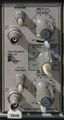
7A18 Front
-
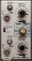
7A18A Front
-
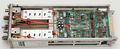
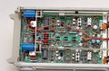
7A18A left side. The step attenuators can be seen on the left, the amplifier board on the right.
-

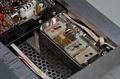
7A18A right side. The circuit boards on top carry the readout circuitry.
-
7A18 attenuator opened. One of the attenuation R/C modules has been unplugged to reveal the switch contacts.
-
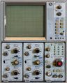
A 7603 with two 7A18s
-

7A18 in 7613 mainframe


Option 06
-

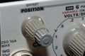
7A18A Opt.06 Front. AC/GND/DC switches have an extra rightmost "DC Offset" position enabling the offset controls.
-
7A18A Opt.06 left side (rear). Note the two blue 10T-potentiometers for offset voltage adjustment.
-
7A18A Opt.06 - offset controls take the place of the Identify buttons on the standard model.


