7A24: Difference between revisions
No edit summary |
No edit summary |
||
| Line 50: | Line 50: | ||
Tek 7a24 2.jpg | Tek 7a24 2.jpg | ||
Tek 7a24 3.jpg | Tek 7a24 3.jpg | ||
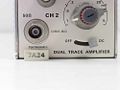
7a24 front.jpg | Front | 7a24 front.jpg | Front | ||
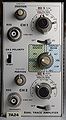
7a24 frontend.jpg | Attenuator switches | 7a24-left.jpg | Left side (later version) | ||
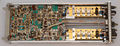
7a24 left board.jpg |Amplifier board | 7a24-right.jpg | Right side (later version) | ||
7a24 frontend.jpg | Attenuator switches | |||
7a24 left board.jpg | Amplifier board | |||
7a24 right front.jpg | Right front | 7a24 right front.jpg | Right front | ||
7a24 right rear.jpg | Right rear | 7a24 right rear.jpg | Right rear | ||
7a24-signal-out.jpg | [[Tektronix Cartoons | Cartoon]] in schematic: Signal Out | 7a24-signal-out.jpg | [[Tektronix Cartoons | Cartoon]] in schematic: Signal Out | ||
</gallery> | </gallery> | ||
[[Category:7000 series vertical plugins]] | [[Category:7000 series vertical plugins]] | ||
Revision as of 14:13, 16 June 2018
The Tektronix 7A24 is a 400 MHz dual-channel vertical plug-in for 7000-series scopes with (fused) 50 Ω BNC inputs. It is the fastest multi-channel plug-in available for the 7000 series. Unlike most other plug-ins, it does not offer AC input coupling.
The 7A24 would typically have been used in 7834, 7844 or 7854 mainframes. The recommended probes were the P6056 and P6057.
The 75 MHz 7A18 and 200 MHz 7A26 share the same front panel layout and operation (but have 1 MΩ inputs).
Key Specifications
| Bandwidth | 400 MHz (71xx) / 350 MHz (79xx) / 300 MHz (78xx) |
|---|---|
| Deflection | 5 mV/Div to 1 V/Div (1–2–5), variable ×2.5 (up to 2.5 V/Div) |
| Input impedance | 50 Ω |
| Maximum input | 5 V (0.5 W) − no damage below 10 V (2 W) |
| Timing | Delay difference between channels < 200 ps |
Internals
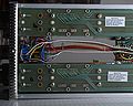
The 7A24's input attenuators are similar to that in the 7A19, using replaceable ceramic attenuator modules held to the switching PCB using steel springs.
The amplifier is built using the Tek-made differential amplifier 155-0078-10 (four units per channel in early, five in late versions). In the 5 mV/Div range only, the amplifier gain is doubled electronically. The signal trace layout on the PCB is designed to provide T-coil peaking.
The 7A24 does not use the ±50 V supplies provided by the mainframe.
Links
Pictures
-

-

-
-
Front
-
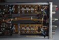
Left side (later version)
-
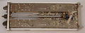
Right side (later version)
-
Attenuator switches
-
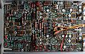
Amplifier board
-
Right front
-
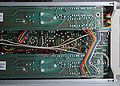
Right rear
-
Cartoon in schematic: Signal Out


