7B92: Difference between revisions
No edit summary |
No edit summary |
||
| (30 intermediate revisions by 4 users not shown) | |||
| Line 1: | Line 1: | ||
{{Plugin Sidebar | {{Plugin Sidebar | ||
|manufacturer=Tektronix | |||
summary=500 MHz | |type=7B92 | ||
image= | |summary=500 MHz dual timebase | ||
caption= | |image=Tek 7b92 front.jpg | ||
introduced=1971 | | |caption=7B92 front | ||
discontinued= | |introduced=1971 | ||
series= | |discontinued=1976 | ||
manuals= | |series=7000-series scopes | ||
* [ | |designers=Bill DeVey;Val Garuts | ||
* [ | |manuals= | ||
'''7B92''' | |||
* [ | * [[Media:070-1401-00.pdf|Tektronix 7B92 Operators Manual]] | ||
* [[Media:070-1192-00.pdf|Tektronix 7B92 Service Manual]] (OCR, uncut schematics) | |||
* [[Media:070-1630-00.pdf|Tektronix 7B92 Circuit Description Supplement]] | |||
}} | }} | ||
The '''Tektronix 7B92''' is a 500 MHz dual timebase plug-in for [[7000-series scopes]]. | The '''Tektronix 7B92''' is a 500 MHz dual timebase plug-in for [[7000-series scopes]]. | ||
It was introduced along with the [[7904]] mainframe in 1972. | It was introduced along with the [[7904]] mainframe in 1972. | ||
According to [[Media:Tekscope 1971 V3 N4 Jul 1971.pdf|July 1971 Tekscope]], the 7B92 was designed by [[Les Larson]] and [[Bill DeVey]]. | |||
An "HF Sync" triggering mode is provided in which the trigger level | An "HF Sync" triggering mode is provided in which the trigger level control varies the frequency of a built-in oscillator to lock on to the input for input signals from 100 to 500 MHz, providing higher sensitivity than the direct trigger (which is specified up to 500 MHz as well). | ||
control varies the frequency of a built-in oscillator to lock on to the input | |||
for | |||
direct trigger (which is specified up to 500 MHz as well). | |||
Internal jumpers are provided to configure the 7B92 for operation in 7800/7900 vs. slower mainframes, | Internal jumpers are provided to configure the 7B92 for operation in 7800/7900 vs. slower mainframes, and to select whether the variable control affects the delaying or the delayed time base. | ||
and to select whether the variable control affects the delaying or the delayed time base. | |||
As a dual time base, the 7B92 uses the top field in the [[7000 series readout system|display readout]] | As a dual time base, the 7B92 uses the top field in the [[7000 series readout system|display readout]] for the sweep speed of the main and the bottom field for the delayed time base. | ||
for the sweep speed of the main and the bottom field for the delayed time base. The delay time | The delay time can only be read from the 10-turn analog dial. | ||
can only be read from the 10-turn analog dial. | |||
The 7B92 has no magnifier function but its regular sweep dial setting reaches down to 500 ps/Div. | The 7B92 has no magnifier function but its regular sweep dial setting reaches down to 500 ps/Div. It has no provision for X-Y operation. | ||
It | |||
{{BeginSpecs}} | {{BeginSpecs}} | ||
{{Spec | Sweep speed | 0.5 ns/Div to 0.2 s/Div, | {{Spec | Sweep speed | 0.5 ns/Div to 0.2 s/Div, 1−2−5 sequence (variable up to 0.5 s/Div)}} | ||
{{Spec | Delay time | 0 to 9.9 Div }} | {{Spec | Delay time | 0 to 9.9 Div }} | ||
{{Spec | Triggering | 0.5 Div or 100 mV up to 20 MHz, 1 Div or 500 mV up to 600 MHz }} | {{Spec | Triggering | 0.5 Div or 100 mV up to 20 MHz, 1 Div or 500 mV up to 600 MHz }} | ||
{{Spec | Jitter | < 50 ps at 600 MHz }} | {{Spec | Jitter | < 50 ps at 600 MHz }} | ||
{{Spec | Ext Trig input | 1 MΩ // 20 pF or 50 Ω }} | {{Spec | Ext Trig input | 1 MΩ // 20 pF or 50 Ω }} | ||
{{EndSpecs}} | {{EndSpecs}} | ||
After the 7B92 had been in production for years, it was discovered that the 7B92's ramp generator | |||
had aberrations at the beginning of the sweep at the fastest sweep rates. | |||
[https://vintagetek.org/years-at-tektronix-hofer/ Bruce Hofer recalls] investigating this issue and | |||
concluding that an redesign was needed. | |||
The redesign led to the introduction of the [[7B92A]], [[Patent US 4009399A]], | |||
and the [[067-0657-00]] calibration fixture. | |||
==Internals== | ==Internals== | ||
The 7B92 uses a discrete trigger circuit containing [[tunnel diodes]]. | The 7B92 uses a discrete trigger circuit containing [[152-0177-02]] [[tunnel diodes]]. | ||
The internal jumper (J308/J309) for mainframe selection (7800/7900/7100 vs. slower) | |||
increases the minimum holdoff time on the slower mainframe selection by adding a 150 pF capacitor, C307, | |||
to pin 8 (HO TIMING) of the sweep control IC, U310 ([[155-0049-00|155-0049-xx]]), in parallel to the existing capacitors. | |||
This increases the minimum pulse width of the holdoff signal on [[7000_Series_plug-in_interface|pin B4]] | |||
so that the sweep logic of slower mainframes can handle it properly. | |||
The effect of this jumper is only noticeable for sweep speeds of 20 μs/Div and faster, | |||
since at those sweep speeds the smallest shunt capacitance is used on pin 8, and the holdoff time is minimal. | |||
==Pictures== | ==Pictures== | ||
<gallery> | <gallery> | ||
Tek 7b92 front.jpg | 7B92 front | Tek 7b92 front.jpg | 7B92 front | ||
Tek 7b92 right.jpg | 7B92 right | Tek 7b92 right.jpg | 7B92 right | ||
Tek 7b92 left.jpg | 7B92 left | Tek 7b92 left.jpg | 7B92 left | ||
</gallery> | </gallery> | ||
==Components== | |||
{{Parts|7B92}} | |||
[[Category:7000 series horizontal plugins]] | [[Category:7000 series horizontal plugins]] | ||
Latest revision as of 07:32, 12 December 2023

The Tektronix 7B92 is a 500 MHz dual timebase plug-in for 7000-series scopes. It was introduced along with the 7904 mainframe in 1972. According to July 1971 Tekscope, the 7B92 was designed by Les Larson and Bill DeVey.
An "HF Sync" triggering mode is provided in which the trigger level control varies the frequency of a built-in oscillator to lock on to the input for input signals from 100 to 500 MHz, providing higher sensitivity than the direct trigger (which is specified up to 500 MHz as well).
Internal jumpers are provided to configure the 7B92 for operation in 7800/7900 vs. slower mainframes, and to select whether the variable control affects the delaying or the delayed time base.
As a dual time base, the 7B92 uses the top field in the display readout for the sweep speed of the main and the bottom field for the delayed time base. The delay time can only be read from the 10-turn analog dial.
The 7B92 has no magnifier function but its regular sweep dial setting reaches down to 500 ps/Div. It has no provision for X-Y operation.
Key Specifications
| Sweep speed | 0.5 ns/Div to 0.2 s/Div, 1−2−5 sequence (variable up to 0.5 s/Div) |
|---|---|
| Delay time | 0 to 9.9 Div |
| Triggering | 0.5 Div or 100 mV up to 20 MHz, 1 Div or 500 mV up to 600 MHz |
| Jitter | < 50 ps at 600 MHz |
| Ext Trig input | 1 MΩ // 20 pF or 50 Ω |
After the 7B92 had been in production for years, it was discovered that the 7B92's ramp generator had aberrations at the beginning of the sweep at the fastest sweep rates. Bruce Hofer recalls investigating this issue and concluding that an redesign was needed. The redesign led to the introduction of the 7B92A, Patent US 4009399A, and the 067-0657-00 calibration fixture.
Internals
The 7B92 uses a discrete trigger circuit containing 152-0177-02 tunnel diodes.
The internal jumper (J308/J309) for mainframe selection (7800/7900/7100 vs. slower) increases the minimum holdoff time on the slower mainframe selection by adding a 150 pF capacitor, C307, to pin 8 (HO TIMING) of the sweep control IC, U310 (155-0049-xx), in parallel to the existing capacitors. This increases the minimum pulse width of the holdoff signal on pin B4 so that the sweep logic of slower mainframes can handle it properly. The effect of this jumper is only noticeable for sweep speeds of 20 μs/Div and faster, since at those sweep speeds the smallest shunt capacitance is used on pin 8, and the holdoff time is minimal.
Pictures
-
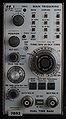
7B92 front
-
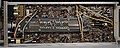
7B92 right
-
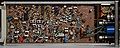
7B92 left
Components
Some Parts Used in the 7B92
| Part | Part Number(s) | Class | Description | Used in |
|---|---|---|---|---|
| 155-0061-00 | 155-0061-00 • 155-0061-01 • 155-0061-02 | Monolithic integrated circuit | trigger amplifier | 7B92 • 7B92A |
| 1N3719 | 152-0182-00 | Discrete component | 10 mA, 50 pF germanium tunnel diode | 422 • 661 • 7B92 • 7B92A |
| SMTD998 | 152-0177-02 | Discrete component | 10 mA, 2 pF tunnel diode | 067-0681-01 • 485 • 7B92 • 7B92A |