7CT1N: Difference between revisions
No edit summary |
|||
| (19 intermediate revisions by 4 users not shown) | |||
| Line 1: | Line 1: | ||
{{Plugin Sidebar | {{Plugin Sidebar | ||
|manufacturer=Tektronix | |||
summary=Curve tracer plug-in | | |series=7000-series scopes | ||
image=tek-7ct1n-front.jpg | | |type=7CT1N | ||
caption=Tektronix 7CT1N | | |summary=Curve tracer plug-in | ||
introduced=1971 | | |image=tek-7ct1n-front.jpg | ||
discontinued=1990 | | |caption=Tektronix 7CT1N | ||
|introduced=1971 | |||
manuals= | |discontinued=1990 | ||
* [ | |designers=Matt Zimmerman | ||
* [ | |manuals= | ||
* [[Media:070-1247-00.pdf|Tektronix 7CT1N Manual]] (OCR) | |||
* [[Media:062-1009-00.pdf|Semiconductor Device Measurements]] (''Concepts'' series) | |||
* [[Media:7CT1N Product Modification Summary.pdf|7CT1N Product Modification Summary]] | |||
}} | }} | ||
The '''Tektronix 7CT1N''' is a | The '''Tektronix 7CT1N''' is a curve tracer plug-in for [[7000-series scopes]]. The [[5CT1N]] plug-in for [[5000-series scopes]] is very similar. | ||
It can be installed in either a vertical or a horizontal compartment, a front-panel switch must be set accordingly. | It can be installed in either a vertical or a horizontal compartment, a front-panel switch must be set accordingly. | ||
A pull-out cable with a plastic BNC plug connects to the input of a module installed in the corresponding | A pull-out cable with a plastic BNC plug connects to the input of a module installed in the corresponding | ||
plugin for the other axis, with a fixed 100 mV/ | plugin for the other axis, with a fixed 100 mV/div scaling compatible with time base X inputs. | ||
Internally, a variable-amplitude 55 Hz triangle-wave source supplies a transformer to step up the drive voltage and | Internally, a variable-amplitude 55 Hz triangle-wave source supplies a transformer to step up the drive voltage and | ||
decouple it from ground (Emitter terminal). A step source supplies base current or gate voltage to the DUT. | decouple it from ground (Emitter terminal). A step source supplies base current or gate voltage to the DUT. | ||
The amplifier for the current axis can be switched into a | |||
to detect leakage currents (of typical 1970s semiconductors, anyway). | The amplifier for the current axis can be switched into a ÷1000 mode to detect leakage currents (of typical 1970s semiconductors, anyway). | ||
{{BeginSpecs}} | {{BeginSpecs}} | ||
{{Spec | DUT drive voltage (C-E) | | {{Spec | DUT drive voltage (C-E) | | ||
* positive (NPN or N channel) or negative (PNP or P channel) half-waves | * positive (NPN or N-channel) or negative (PNP or P-channel) half-waves | ||
* 7.5 V, 0.5 V/ | * 7.5 V, 0.5 V/div, 240 mA peak | ||
* 30 V, 2 V/ | * 30 V, 2 V/div, 60 mA peak | ||
* 75 V, 5 V/ | * 75 V, 5 V/div, 24 mA peak | ||
* 300 V, 20 V/ | * 300 V, 20 V/div, 6 mA peak | ||
* HV warning light on for > 50 V | * HV warning light on for > 50 V | ||
* peak power 500 mW}} | * peak power 500 mW}} | ||
{{Spec | DUT current display | | {{Spec | DUT current display | | ||
* | * 10 μA/div to 20 mA/div, 1−2−5 steps (×1 mode) | ||
* 10 nA/ | * 10 nA/div to 20 μA/div, 1−2−5 steps (÷1000 mode)}} | ||
{{Spec | Base/Gate drive | | {{Spec | Base/Gate drive | | ||
* 0 to at least 10 steps | * 0 to at least 10 steps | ||
* dual polarity | * dual polarity | ||
* variable offset, at least +/ | * variable offset, at least +/− 5 steps | ||
* current mode: | * current mode: 1 μA/step to 1 mA/step in 1−2−5 sequence | ||
* voltage mode: 1 mV/ | * voltage mode: 1 mV/step to 1 V/step in 1−2−5 sequence (via 1 kΩ current limiting resistor) | ||
}} | }} | ||
{{Spec | DUT connection | Three 4 mm jacks / binding posts}} | {{Spec | DUT connection | Three 4 mm jacks / binding posts}} | ||
| Line 54: | Line 57: | ||
==Links== | ==Links== | ||
* [http://amplifier.cd/Test_Equipment/Tektronix/Tektronix_7000_series_special/7CT1N_curve_tracer.htm Tek 7CT1N @ amplifier.cd] | * [http://amplifier.cd/Test_Equipment/Tektronix/Tektronix_7000_series_special/7CT1N_curve_tracer.htm Tek 7CT1N @ amplifier.cd] | ||
* [http://www.antiqueradios.com/forums/viewtopic.php?f=8&t=177192 A homebrew test adapter] | |||
* [[Dennis Tillman]]: ''[http://www.ke5fx.com/A_VTCT_Adapter_for_All_Tektronix_SCTs_W7PF.pdf An Inexpensive Vacuum Tube Curve Tracer Adapter for All Tektronix Semiconductor Curve Tracers]'' | |||
* [http://www.barrytech.com/tektronix/tek7000/tek7ct1n.html Tek 7CT1N @ barrytech.com] | * [http://www.barrytech.com/tektronix/tek7000/tek7ct1n.html Tek 7CT1N @ barrytech.com] | ||
{{Documents|Link=7CT1N}} | |||
{{Documents|Link=Curve tracers}} | |||
==Common Problems== | ==Common Problems== | ||
C30 and C32 (100 μF, 25 V) [http://hakanh.com/dl/docs/hardtofind/CT1N.pdf are under-rated] and therefore have a tendency to leak or short, | C30 and C32 (100 μF, 25 V) [http://hakanh.com/dl/docs/hardtofind/CT1N.pdf are under-rated] and therefore have a tendency to leak or short, | ||
causing associated resistors R30 and R32 ( | causing associated resistors R30 and R32 (240 Ω, 0.25 W, 5%) to overheat and fail. | ||
C30 and C32 should be replaced with modern equivalents rated above 35 V. | C30 and C32 should be replaced with modern equivalents rated above 35 V. | ||
| Line 70: | Line 74: | ||
|- | |- | ||
!Year | !Year | ||
! | ! 1971 | ||
! | ! 1980 | ||
! 1990 | |||
|- | |- | ||
| | !Catalog Price | ||
| align="right" | $ | | align="right" | $400 | ||
| align="right" | $2, | | align="right" | $1,000 | ||
| align="right" | $2,100 | |||
|- | |- | ||
!In 2023 Dollars | |||
| align="right" | $ | | align="right" | $3,000 | ||
| align="right" | $ | | align="right" | $3,600 | ||
| align="right" | $4,900 | |||
| align="right" | $ | |||
|- | |- | ||
|} | |} | ||
| Line 90: | Line 93: | ||
<gallery> | <gallery> | ||
tek-7ct1n-front.jpg | 7CT1N front | tek-7ct1n-front.jpg | 7CT1N front | ||
tek-7ct1n-left.jpg | tek-7ct1n-left.jpg | 7CT1N left side (1979 date codes) | ||
tek-7ct1n-right.jpg | 7CT1N right side | tek-7ct1n-right.jpg | 7CT1N right side | ||
7ct1n-bc337.jpg | 7CT1N LHS 670-1933-01 1984.jpg | 7CT1N LHS (1984 date codes) | ||
7CT1N RHS 670-1933-01 1984.jpg | 7CT1N RHS '84 | |||
Tek 7ct1n schematic2.png | |||
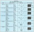
5CT1N 7CT1N Basic Measurement Reference Chart.jpg | |||
</gallery> | |||
'''Measurements''' | |||
<gallery> | |||
7CT1 homemade AB adapter 1.jpg | home-made A/B adapter | |||
7CT1 homemade AB adapter 2.jpg | home-made A/B adapter, rear | |||
7CT1 homemade AB adapter 3.jpg | home-made A/B adapter used to compare two transistors | |||
Home-made 3-pin curve tracer adapter.jpg | Another home-made adapter (see [http://www.antiqueradios.com/forums/viewtopic.php?f=8&t=177192 this thread]) | |||
7CT1N_optocoupler.jpg | 7CT1N tracing a no-name optocoupler | |||
7ct1n-bc337.jpg | 7CT1N tracing a BC337 NPN Si transistor | |||
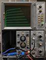
Tek 7ct1n trace.jpg | |||
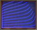
Tek 7ct1n td.jpg | 10 mA tunnel diode. 7A13 is set to 10 mV/div for ×10 horizontal expansion. | |||
</gallery> | </gallery> | ||
Latest revision as of 11:04, 29 January 2024

The Tektronix 7CT1N is a curve tracer plug-in for 7000-series scopes. The 5CT1N plug-in for 5000-series scopes is very similar.
It can be installed in either a vertical or a horizontal compartment, a front-panel switch must be set accordingly. A pull-out cable with a plastic BNC plug connects to the input of a module installed in the corresponding plugin for the other axis, with a fixed 100 mV/div scaling compatible with time base X inputs.
Internally, a variable-amplitude 55 Hz triangle-wave source supplies a transformer to step up the drive voltage and decouple it from ground (Emitter terminal). A step source supplies base current or gate voltage to the DUT.
The amplifier for the current axis can be switched into a ÷1000 mode to detect leakage currents (of typical 1970s semiconductors, anyway).
Key Specifications
| DUT drive voltage (C-E) |
|
|---|---|
| DUT current display |
|
| Base/Gate drive |
|
| DUT connection | Three 4 mm jacks / binding posts |
| DUT adapters |
|
Links
- Tek 7CT1N @ amplifier.cd
- A homebrew test adapter
- Dennis Tillman: An Inexpensive Vacuum Tube Curve Tracer Adapter for All Tektronix Semiconductor Curve Tracers
- Tek 7CT1N @ barrytech.com
Documents Referencing 7CT1N
| Document | Class | Title | Authors | Year | Links |
|---|---|---|---|---|---|
| Tekscope 1971 V3 N5 Sep 1971.pdf | Article | New Products | 1971 | 7L12 • 7CT1N • 5103N • 5A13N • 5A14N • 5A22N • 5CT1N • 172 • 1501 • P6056 • P6057 • 603 • 604 • 4602 • S-3160 | |
| Tekscope 1972 V4 N6 Nov 1972.pdf | Article | Oscilloscope to Curve Tracer with One Plug-in | Matt Zimmerman | 1972 | 5CT1N • 7CT1N |
| 48W-3346-3.pdf | Brochure | Making the Correct Semiconductor Measurements Time After Time | 1982 | 576 • 172 • 176 • 577 • 178 • 5CT1N • 7CT1N |
Documents Referencing Curve tracers
| Document | Class | Title | Authors | Year | Links |
|---|---|---|---|---|---|
| 062-1009-00.pdf | Book | Measurement Concepts: Semiconductor Device Measurements | John Mulvey | 1969 | Curve tracers • Tunnel diodes |
| Tekscope 1969 V1 N1 Feb 1969.pdf | Article | Curve Tracing Displays | 1969 | Curve tracers • 576 | |
| Tekscope 1969 V1 N5 Oct 1969.pdf | Article | Troubleshooting the Sweep Ciruits | Charles Phillips | 1969 | 575 • 576 • Curve tracers |
| Tekscope 1972 V4 N3 May 1972.pdf | Article | Semiautomatic Testing with the Curve Tracer | Jack Millay | 1972 | 576 • 172 • Curve tracers |
| Tektronix Curve Tracers - Device Testing Techniques.pdf | Book | Tektronix Curve Tracers - Device Testing Techniques | 1985 | Curve tracers • Tunnel diodes |
Common Problems
C30 and C32 (100 μF, 25 V) are under-rated and therefore have a tendency to leak or short, causing associated resistors R30 and R32 (240 Ω, 0.25 W, 5%) to overheat and fail. C30 and C32 should be replaced with modern equivalents rated above 35 V.
Prices
| Year | 1971 | 1980 | 1990 |
|---|---|---|---|
| Catalog Price | $400 | $1,000 | $2,100 |
| In 2023 Dollars | $3,000 | $3,600 | $4,900 |
Pictures
-

7CT1N front
-
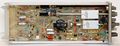
7CT1N left side (1979 date codes)
-
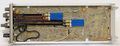
7CT1N right side
-

7CT1N LHS (1984 date codes)
-

7CT1N RHS '84
-

-


Measurements
-
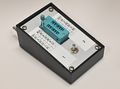
home-made A/B adapter
-
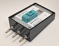
home-made A/B adapter, rear
-
home-made A/B adapter used to compare two transistors
-
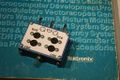
Another home-made adapter (see this thread)
-
7CT1N tracing a no-name optocoupler
-
7CT1N tracing a BC337 NPN Si transistor
-

-
10 mA tunnel diode. 7A13 is set to 10 mV/div for ×10 horizontal expansion.


