7D11: Difference between revisions
(specs template) |
(new picture without BNC covers) |
||
| Line 2: | Line 2: | ||
title=Tektronix 7D11| | title=Tektronix 7D11| | ||
summary=Digital Delay | | summary=Digital Delay | | ||
image= | image=tek-7d11-front.jpg | | ||
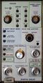
caption=7D11 front view| | caption=7D11 front view| | ||
years=? – ? | | years=? – ? | | ||
| Line 29: | Line 29: | ||
==Pictures== | ==Pictures== | ||
<gallery> | <gallery> | ||
File: | File:tek-7d11-front.jpg|front | ||
File:Tek 7d11 left.JPG|left | File:Tek 7d11 left.JPG|left | ||
File:Tek 7d11 right.JPG|right | File:Tek 7d11 right.JPG|right | ||
Revision as of 03:27, 25 June 2014

The Tektronix 7D11 Digital Delay can be used to delay a 7B timebase by a given time up to 1 second in 100 ns increments, or by a number of events (1 to 1E7 at up to 50 MHz). The selected delay is displayed in the on-screen readout (7 digits). An analog fine delay control can add from 0 to 100 ns in delay mode. The 7D11 has an internal reference oscillator or can accept an external 1 MHz input.
For internal triggering, the 7D11 must be operated in the A Horizontal compartment (of a four-bay mainframe) to control the delay mode of a timebase in the B Horizontal compartment. If installed in a Vertical compartment, it can display the "Delay Interval Pedestal" as its Y output signal (centered on screen, no position control) and can supply a trigger signal to a timebase in either Horizontal compartment. However, since mainframes do not route internal trigger signals to Vertical bays, the 7D11 itself must be triggered externally in this case (which is the only possibility to use it in a three-bay mainframe).
Two switches internal to the 7D11 allow the user to enable Z axis modulation and "Echo mode" to double the indicated delay, respectively. The latter is provided for radar or TDR applications where the delay time of the reflected pulse is twice the cable delay.
Specifications
Key Specifications
| Delay time | 100 ns to 1 s in 100 ns increments (0-100 ns analog fine control) |
|---|---|
| Events mode | 1 to 107 counts controlled by separate Events Start input |
| Event count or trigger input | max. 50 MHz |
| Trigger | 150 mV to 10 MHz, 500 mV to 50 MHz (0.3 Div / 1 Div respectively for internal triggering); LF REJ 30 kHz, HF REJ 50 kHz |
| Internal reference | 5 MHz +/- 0.5 ppm, drift < 10-7 per month |
| Jitter | < 2.2 ns or delay * 10-7 (whichever is greater) |
Pictures
-
front
-

left
-
right