7L18: Difference between revisions
No edit summary |
No edit summary |
||
| (24 intermediate revisions by 3 users not shown) | |||
| Line 1: | Line 1: | ||
{{Plugin Sidebar | {{Plugin Sidebar | ||
|manufacturer=Tektronix | |||
summary=18 (60) GHz Spectrum Analyzer | | |series=7000-series scopes | ||
image=7L18-front.jpg | | |type=7L18 | ||
caption=Tektronix 7L18 | | |summary=18 (60) GHz Spectrum Analyzer | ||
introduced= | |image=7L18-front.jpg | ||
discontinued=1984 | | |caption=Tektronix 7L18 | ||
|introduced=1978 | |||
|discontinued=1984 | |||
*[ | |designers=Linley Gumm;Bob Bales;Russell Brown;George Maney;Carlos Beeck;James Wolf;Dave Shores;Philip Snow;Wesley Hayward;Jack Reynolds;Steve Morton;Don Kirkpatrick;Dennis Smith;Al Huegli; | ||
*[ | |manuals= | ||
* [[Media:070-2295-00.pdf|7L18 Service Manual]] | |||
* [[Media:070-2339-02.pdf|7L18 Operators Manual]] (OCR) | |||
* [[Media:061-1469-02.pdf|7L18 Interim Service Manual]] (OCR) | |||
* [[Media:Tek tracking the wild preselector 7L18.pdf|Tracking the Wild Preselector in Its Native Habitat - The 7L18]] | |||
* [[Media:Tek 7L18 Opt1.pdf|Digital Interfacing for the 7L18]] | |||
{{ROM Images}} | |||
* [[Media:7L18 PROMs.zip|7L18 PROMs 156-1128-00 (U367) and 156-1129-00 (U369), ZIP of two Intel HEX files]] | |||
}} | }} | ||
The '''Tektronix 7L18''' is a spectrum analyzer plug-in [[introduced in 1978]] for [[7000-series scopes]]. | The '''Tektronix 7L18''' is a spectrum analyzer plug-in [[introduced in 1978]] for [[7000-series scopes]]. It occupies three plug-in bays in the oscilloscope. | ||
{{BeginSpecs}} | |||
using external mixers | {{Spec | Frequency range | 1.5 GHz to 18 GHz with the internal mixer, 12.5 GHz to 60 GHz using external mixers }} | ||
{{Spec | Frequency span | 0; 200 Hz/Div to 500 MHz/Div in 1−2−5 steps; Max (see note below) }} | |||
{{Spec | Resolution bandwidth | 30 Hz to 3 MHz in decade steps}} | |||
{{Spec | Vertical scale | 10 dB/Div, 2 dB/Div, or linear }} | |||
{{Spec | Input attenuator | 0 dB to 60 dB in 10 dB steps }} | |||
{{Spec | Sweep | 1 μs/Div to 20 s/Div, auto, ext, or manual }} | |||
{{Spec | Digital functions | two memory banks (A, B); Display A, B - A saved, peak hold }} | |||
{{EndSpecs}} | |||
''Please expand '' | |||
==Context== | |||
[[Linley Gumm]] says: | |||
<blockquote>Another disappointment was the 7L18 microwave analyzer project, one of the earliest Tek products to have a microprocessor in it. | |||
"We started work on developing this product in 1974, and finally shipped our first instrument in 1978. | |||
As I look back, it was a terribly crude microprocessor, and we made every error in the book. | |||
Of course, we didn't have any of the tools that are available today." | |||
Although the 7L18 never did sell well, Linley and his crew developed components and technologies that later were used in the [[492]]. | |||
([[Media:LinleyGumm_TW_03271987.pdf|TekWeek March 27, 1987]]) | |||
</blockquote> | |||
<blockquote> | |||
As Project Manager for the 7L18 I would like to express my thanks to those who contributed so much to the success of the project. | |||
[[Bob Bales]] worked on the sweep, span attenuator, YIG driver, and instrument-interconnect; [[Russell Brown]] and [[George Maney]] did the microprocessor programming; [[Carlos Beeck]] and [[James Wolf]] mechanical design of the microwave assemblies, with [[Dave Shores]] and [[Philip Snow]] providing the electrical design; IF design was done by [[Wesley Hayward]]; [[Jack Reynolds]] | |||
was involved in the early design of the phase lock circuitry with [[Steve Morton]] completing the work; [[Don Kirkpatrick]] designed the digital storage ICs with [[Dennis Smith]] doing the front panel and digital storage board; [[Al Huegli]] was responsible for the outstanding job of mechanical design. [[Virginia Morehead]] was indispensable in providing prototype support, as were the plant support people during introduction. Many other names should be included in this list but space doesn't allow. | |||
([[Media:Tekscope 1977 V9 N3.pdf|Tekscope 1977 V9 N3]]) | |||
</blockquote> | |||
==Internals== | ==Internals== | ||
The LO is a YIG tuned oscillator covering the 2 GHz to 4 GHz range. | |||
Its output passes through a sampler assembly used to PLL the YIG on small resolution bandwidths. | |||
The output of the sampler goes to the LO input on the mixer. The mixer IF output is 510 MHz. | |||
The 7L18's components are controlled by an [[Intel 4004]] 4-bit microprocessor. | The 7L18's components are controlled by an [[Intel 4004]] 4-bit microprocessor. | ||
The 7L18 will NOT do 1.5 GHz to 18 GHz in one span, it will only max span the range selected by the BAND/HARMONIC control. This range is determined by the heterodyne harmonic number and sign (sideband) and the range of the first LO, which is 2 GHz to 4 GHz. | |||
The input attenuator is a standard Weinschel Engineering product driven by a belt. | |||
The range is encoded for the digital dBm reference level display. | |||
The signal then passes through a YIG preselector filter with a 50 MHz bandwidth. | |||
After the YIG filter, the signal enters the RF input of the mixer assembly. | |||
==Links== | ==Links== | ||
* [ | * [https://w140.com/tektronix_spectrum_analysis_using_waveguide_mixers.pdf Spectrum Analysis Using Waveguide Mixers] | ||
* [[016-0631-01|Waveguide Mixers for 492 and 7L18]] | |||
{{Documents|Link=7L18}} | |||
==Prices== | |||
{| class="wikitable" | |||
|- | |||
! Year | |||
! 1978 | |||
! 1980 | |||
! 1982 | |||
! 1984 | |||
|- | |||
! Catalog price | |||
| align="right" | $12,600 | |||
| align="right" | $14,600 | |||
| align="right" | $17,500 | |||
| align="right" | $19,400 | |||
|- | |||
! In 2023 Dollars | |||
| align="right" | $59,300 | |||
| align="right" | $54,400 | |||
| align="right" | $55,700 | |||
| align="right" | $57,300 | |||
|- | |||
|} | |||
==Pictures== | ==Pictures== | ||
<gallery> | |||
Tek 7l18 3822 1.jpg | |||
Tek 7l18 3822 2.jpg | |||
Tek 7l18 3822 3.jpg | |||
Tek 7l18 3822 4.jpg | |||
Tek 7l18 3822 5.jpg | |||
Tek 7l18 3822 6.jpg | |||
Tek 7l18 3822 7.jpg | |||
Tek 7l18 3822 8.jpg | |||
Tek 7l18 3822 9.jpg | |||
Tek 7l18 3822 10.jpg | |||
Tek 7l18 3822 11.jpg | |||
Tek 7l18 3822 12.jpg | |||
</gallery> | |||
Service views: | Service views: | ||
<gallery> | <gallery> | ||
7L18-top.jpg|Top view | |||
7L18-bottom.jpg|Bottom view | |||
7L18-service-rightfront.jpg|Service setup for the right front panel | |||
</gallery> | </gallery> | ||
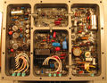
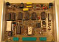
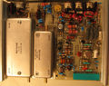
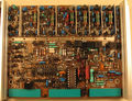
Boards within the digital card cage (from back to front): | Boards within the digital card cage (from back to front): | ||
<gallery> | <gallery> | ||
7L18-board-crtreadout.jpg|CRT Readout board | |||
7L18-board-centerfreqreadout.jpg|Center Freq Readout board | |||
7L18-board-sweephoriz.jpg|Sweep Horiz board | |||
7L18-board-spanatten.jpg|Span Atten board | |||
7L18-board-phaselock-rear.jpg|Phase Lock module, rear | |||
7L18-board-phaselock-front.jpg|Phase Lock module, front | |||
7L18-board-phaselocklogicctl.jpg|Phase Lock Logic CTL | |||
7L18-board-vrnoisefilter.jpg|VR Noise Filter | |||
7L18-board-logvideoamp.jpg|Log & Video Amp | |||
7L18-board-centerfreqdvm.jpg|Center Freq DVM | |||
7L18-board-centerfreqdvm-front.jpg|Digital Storage, front | |||
7L18-board-centerfreqdvm-back.jpg|Digital Storage, back | |||
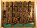
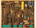
7L18-board-microcomputer.jpg|Micro Computer | |||
</gallery> | </gallery> | ||
| Line 73: | Line 141: | ||
Internal views of the analog parts: | Internal views of the analog parts: | ||
<gallery> | <gallery> | ||
7L18-sampler.jpg|Internal of the LO sampler | |||
</gallery> | </gallery> | ||
==Components== | |||
{{Parts|7L18}} | |||
[[Category:7000 series combined plugins]] | [[Category:7000 series combined plugins]] | ||
[[Category: | [[Category:7000 series spectrum analyzer plugins]] | ||
Latest revision as of 08:31, 7 March 2024

The Tektronix 7L18 is a spectrum analyzer plug-in introduced in 1978 for 7000-series scopes. It occupies three plug-in bays in the oscilloscope.
Key Specifications
| Frequency range | 1.5 GHz to 18 GHz with the internal mixer, 12.5 GHz to 60 GHz using external mixers |
|---|---|
| Frequency span | 0; 200 Hz/Div to 500 MHz/Div in 1−2−5 steps; Max (see note below) |
| Resolution bandwidth | 30 Hz to 3 MHz in decade steps |
| Vertical scale | 10 dB/Div, 2 dB/Div, or linear |
| Input attenuator | 0 dB to 60 dB in 10 dB steps |
| Sweep | 1 μs/Div to 20 s/Div, auto, ext, or manual |
| Digital functions | two memory banks (A, B); Display A, B - A saved, peak hold |
Please expand
Context
Linley Gumm says:
Another disappointment was the 7L18 microwave analyzer project, one of the earliest Tek products to have a microprocessor in it.
"We started work on developing this product in 1974, and finally shipped our first instrument in 1978. As I look back, it was a terribly crude microprocessor, and we made every error in the book. Of course, we didn't have any of the tools that are available today."
Although the 7L18 never did sell well, Linley and his crew developed components and technologies that later were used in the 492.
As Project Manager for the 7L18 I would like to express my thanks to those who contributed so much to the success of the project. Bob Bales worked on the sweep, span attenuator, YIG driver, and instrument-interconnect; Russell Brown and George Maney did the microprocessor programming; Carlos Beeck and James Wolf mechanical design of the microwave assemblies, with Dave Shores and Philip Snow providing the electrical design; IF design was done by Wesley Hayward; Jack Reynolds was involved in the early design of the phase lock circuitry with Steve Morton completing the work; Don Kirkpatrick designed the digital storage ICs with Dennis Smith doing the front panel and digital storage board; Al Huegli was responsible for the outstanding job of mechanical design. Virginia Morehead was indispensable in providing prototype support, as were the plant support people during introduction. Many other names should be included in this list but space doesn't allow.
Internals
The LO is a YIG tuned oscillator covering the 2 GHz to 4 GHz range. Its output passes through a sampler assembly used to PLL the YIG on small resolution bandwidths. The output of the sampler goes to the LO input on the mixer. The mixer IF output is 510 MHz.
The 7L18's components are controlled by an Intel 4004 4-bit microprocessor.
The 7L18 will NOT do 1.5 GHz to 18 GHz in one span, it will only max span the range selected by the BAND/HARMONIC control. This range is determined by the heterodyne harmonic number and sign (sideband) and the range of the first LO, which is 2 GHz to 4 GHz.
The input attenuator is a standard Weinschel Engineering product driven by a belt. The range is encoded for the digital dBm reference level display. The signal then passes through a YIG preselector filter with a 50 MHz bandwidth. After the YIG filter, the signal enters the RF input of the mixer assembly.
Links
Documents Referencing 7L18
| Document | Class | Title | Authors | Year | Links |
|---|---|---|---|---|---|
| Tekscope 1977 V9 N3.pdf | Article | Digital Storage for a Microwave Spectrum Analyzer | Dennis Smith • Don Kirkpatrick | 1977 | 7L18 • 7L5 • 155-0157-00 • 155-0158-00 |
| Tekscope 1977 V9 N3.pdf | Article | A Phase Lock Stabilization System for 30 Hz Resolution at 12 GHz | Morris Engelson • Steve Morton | 1977 | 7L18 |
| Tekscope 1977 V9 N3.pdf | Article | A High Performance Transportable Microwave Spectrum Analyzer | Linley Gumm | 1977 | 7L18 |
Prices
| Year | 1978 | 1980 | 1982 | 1984 |
|---|---|---|---|---|
| Catalog price | $12,600 | $14,600 | $17,500 | $19,400 |
| In 2023 Dollars | $59,300 | $54,400 | $55,700 | $57,300 |
Pictures


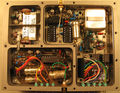
Service views:
-
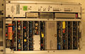
Top view
-
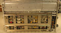
Bottom view
-
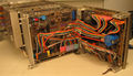
Service setup for the right front panel


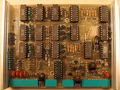
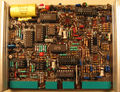
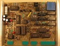
Boards within the digital card cage (from back to front):
-
CRT Readout board
-
Center Freq Readout board
-
Sweep Horiz board
-
Span Atten board
-
Phase Lock module, rear
-
Phase Lock module, front
-
Phase Lock Logic CTL
-
VR Noise Filter
-
Log & Video Amp
-
Center Freq DVM
-
Digital Storage, front
-
Digital Storage, back
-
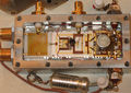
Micro Computer


The microcomputer board is built using three very old Intel chips: an Intel 4004 processor, an Intel 4002 320-bit RAM and 4-bit output port, and an Intel D4289 standard memory interface. The D4289 connects the 4004 to the two 2K8 ROMs. Note that in an earlier version of the 7L18 there were 6 ROMs.
Internal views of the analog parts:
-
Internal of the LO sampler

Components
Some Parts Used in the 7L18
| Part | Part Number(s) | Class | Description | Used in |
|---|---|---|---|---|
| 155-0028-00 | 155-0028-00 • 155-0028-01 • 155-0042-00 • 155-0042-01 • 155-0042-02 • 155-0042-03 | Monolithic integrated circuit | Miller integrator and delay pickoff | 5030 • R5030 • 5031 • R5031 • 1401 • 1401A • 1480 • 1481 • 1482 • 1485 • 26G1 • 26G2 • 26G3 • 314 • 335 • 432 • 434 • 4701 • 5B10N • 5B12N • 5B31 • 5B40 • 5B42 • 5S14N • 7B52 • 7B53A • 7B53N • 7L12 • 7L13 • 7L14 • 7L18 • 7S14 • AN/USM-281C • RG501 • Telequipment D63 • Telequipment DM63 |
| 155-0035-00 | 155-0035-00 • 155-0116-00 | Monolithic integrated circuit | quad op-amp | 3110 • 3S7 • 3T7 • 492 • 492A • 492AP • 492P • 494 • 494P • 496 • 496P • 4010 • 4011 • 4012 • 4013 • 7L5 • 7L12 • 7L13 • 7L14 • 7L18 • 7S11 • 7T11 • 7S12 • S-6 • 1461 • 4602 • P7001 • 613 • 653 |
| 155-0056-00 | 155-0056-00 • 155-0056-01 | Monolithic integrated circuit | sweep control | 26G1 • 26G2 • 26G3 • 314 • 4701 • 5B10N • 5B12N • 5S14N • 7L5 • 7L12 • 7L13 • 7L14 • 7L18 • 7S14 • 5S14N • RG501 • Telequipment D63 • Telequipment DM63 |
| 155-0157-00 | 155-0157-00 | Monolithic integrated circuit | digital storage vertical control | 7L5 • 7L14 • 7L18 • 491 • 492 • 492A • 492BP • 492PGM • 494 • 494A • 495 • 496 • 497P |
| 155-0158-00 | 155-0158-00 | Monolithic integrated circuit | digital storage horizontal control | 7L5 • 7L14 • 7L18 • 491 • 492 • 492A • 492BP • 492PGM • 494 • 494A • 495 • 496 • 497P |
| Fairchild 3814 | 156-0306-00 | Monolithic integrated circuit | 4½ digit dual-slope DVM controller | 7A13 • 7L13 • 7L18 • DM501 |
| Intel 4004 | Monolithic integrated circuit | 4-bit microprocessor | 7L18 |