7S14: Difference between revisions
No edit summary |
|||
| Line 11: | Line 11: | ||
* [http://w140.com/7s14_instruction.pdf Tektronix 7S14 Instruction Manual (PDF)] | * [http://w140.com/7s14_instruction.pdf Tektronix 7S14 Instruction Manual (PDF)] | ||
}} | }} | ||
The '''Tektronix 7S14''' is a 1 GHz dual-trace delayed sweep sampler plug-in. | The '''Tektronix 7S14''' is a 1 GHz dual-trace delayed sweep sampler plug-in. | ||
It is almost identical to the [[5S14]] plugin for the [[5000-series_scopes|5000 series]]. | |||
It is a complete sampling system unlike, for example, the [[ | It is a complete sampling system unlike, for example, the [[7S11]], | ||
which requires a separate timing plug-in to provide triggering | which requires a separate timing plug-in to provide triggering | ||
and sampling pulse generation. | and sampling pulse generation. | ||
| Line 33: | Line 34: | ||
==Internals== | ==Internals== | ||
The 7S14 contains two samplers, trigger and sweep circuitry, and circuitry to interface it with the 7000-series mainframe in which it operates. The mainframe provides the 7S14 with power. | The 7S14 contains two samplers, trigger and sweep circuitry, | ||
and circuitry to interface it with the 7000-series mainframe in which it operates. | |||
The mainframe provides the 7S14 with power. | |||
The 7S14 sends the mainframe horizontal, vertical and readout signals. | |||
The 7S14 has an integrated delay measurement function. | The 7S14 has an integrated delay measurement function. | ||
| Line 40: | Line 44: | ||
In triggered mode, the signal passes through two stages of | In triggered mode, the signal passes through two stages of | ||
[[MC1672]] ECL logic gate, and then into the [[155-0109]] trigger chip. | [[MC1672]] ECL logic gate, and then into the [[155-0109]] trigger chip. | ||
In HF-sync mode, the 7S14 uses a [[BD4]] back diode (0.1 mA, 3 pF), and inductor, and a | In HF-sync mode, the 7S14 uses a [[BD4]] back diode (0.1 mA, 3 pF), and inductor, | ||
[[152-0177-00]] tunnel diode (10 mA, 4 pF) to form an oscillator that oscillates | and a [[152-0177-00]] tunnel diode (10 mA, 4 pF) to form an oscillator | ||
somewhere between 16.5 MHz and 25 MHz. | that oscillates somewhere between 16.5 MHz and 25 MHz. | ||
The sampler used by the 7S14 is a two-diode design. | The sampler used by the 7S14 is a two-diode design. | ||
Revision as of 07:14, 14 February 2018
Template:Plugin Sidebar 2 The Tektronix 7S14 is a 1 GHz dual-trace delayed sweep sampler plug-in. It is almost identical to the 5S14 plugin for the 5000 series.
It is a complete sampling system unlike, for example, the 7S11, which requires a separate timing plug-in to provide triggering and sampling pulse generation.
Key Specifications
| Rise time | 350 ps (1 GHz bandwidth) |
|---|---|
| Trigger bandwidth | 100 MHz (Norm/Auto trigger), 1 GHz (HF sync) |
| Vertical deflection | 2 mV/Div to 0.5 V/Div in 1—2—5 sequence |
| Sweep rate | 100 µs/Div to 100 ps/Div in 1—2—5 sequence |
| Input impedance | 50 Ω |
| Maximum input voltage | 5 V peak |
| Features |
|
Internals
The 7S14 contains two samplers, trigger and sweep circuitry, and circuitry to interface it with the 7000-series mainframe in which it operates. The mainframe provides the 7S14 with power. The 7S14 sends the mainframe horizontal, vertical and readout signals.
The 7S14 has an integrated delay measurement function.
The 7S14 has two triggering modes: triggered and HF-sync. In triggered mode, the signal passes through two stages of MC1672 ECL logic gate, and then into the 155-0109 trigger chip. In HF-sync mode, the 7S14 uses a BD4 back diode (0.1 mA, 3 pF), and inductor, and a 152-0177-00 tunnel diode (10 mA, 4 pF) to form an oscillator that oscillates somewhere between 16.5 MHz and 25 MHz.
The sampler used by the 7S14 is a two-diode design. Each of the two input channels has its own sampler. The sampling diodes are in CR1A and CR1B of dual diode 152-0572-00.
Repair issues
There are two 1.35 V mercury button cells, BT1 and BT2, in each of the sampler circuits. They act as floating bias sources, so if a 7S14 stops working it may be not defective, just the batteries are likely to be dead. First check the voltage on the cells. The original mercury cells can be replaced with other (less toxic) methods of bias voltage generation. Two obvious solutions are photovoltaic cells or modern batteries. The issue has been discussed extensively on the Yahoo TekScopes forum, so search the archives there for more information. Notably, Ed Breya posted detailed notes on the 7S14 bias cell issue.
Links
Prices
| Year | 1974 | 1980 | 1988 |
|---|---|---|---|
| Catalog price | $1,850 | $3,200 | $6,490 |
| 2017 value | $9,200 | $9,520 | $13,450 |
Pictures
-
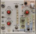
7S14 front panel
-
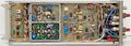
Left side
-
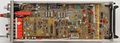
Right side
-
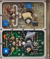
Sampler boards detail with cover removed
-
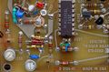
Trigger board detail - tunnel diode oscillator (CR220, CR221, L220)
-
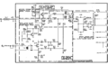
Sampler schematic
-
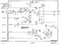
Trigger schematic


