ACVS: Difference between revisions
No edit summary |
|||
| Line 24: | Line 24: | ||
== ACVS in 11000-Series Mainframes == | == ACVS in 11000-Series Mainframes == | ||
In | In 11300 mainframes, the ACVS is controlled by an 8051-family microcontroller. | ||
It employs a [[Media:DAC312.pdf|DAC312]] 12-bit DAC, | It employs a [[Media:DAC312.pdf|DAC312]] 12-bit DAC, | ||
whose output is fed to an array of | whose output is fed to an array of 32 sample-and-hold circuits similar to the ones in the plug-ins. | ||
A refresh cycle sequentially refreshes the voltage on each of the sample-and-hold capacitors. | A refresh cycle sequentially refreshes the voltage on each of the sample-and-hold capacitors. | ||
The time to complete the entire refresh cycle is 900 μs. | The time to complete the entire refresh cycle is 900 μs. | ||
The precision | The precision of each sample-and-hold voltage 12 bits. | ||
26 of the sample-and-hold voltages are used independently. | |||
These | Six of the voltages are combined in groups of three, using resistor summing networks, | ||
to produce two outputs that each have 14.6 bit precision. | |||
These two precision voltages are DLYREF0 and DLYREF1, | |||
which are compared with the sweep ramp to generate sweep delay pulse. | |||
In earlier analog scopes (e.g., the [[565]]), | |||
the precision DC control voltage for the delay ramp comparator | |||
was produced by a multi-turn potentiometer on the front panel. | |||
<gallery> | <gallery> | ||
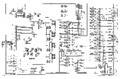
Tek 11300 acvs.png|ACVS schematic in 11300 mainframes | Tek 11300 acvs.png|ACVS schematic in 11300 mainframes | ||
Tek 11300 dlyref3.png|The weighted sum of three ACVS voltages is fed to the delay ramp comparator | |||
</gallery> | </gallery> | ||
[[Category:Circuits and Concepts]] | [[Category:Circuits and Concepts]] | ||
Revision as of 09:46, 27 April 2018
Tektronix 11000-series plug-ins and mainframes contain a subsystem called the Analog Control Voltage System (ACVS). The ACVS produces several independently controllable DC voltages. The voltages are fed to the analog signal path circuitry (e.g., the OFFSET input of the M377, or the OFFSET pin on the TekProbe input connector. The number of voltages produced by the ACVS depends on how many channels the plug-in has. For example, the 11A34, which has four channels, has an ACVS that produces sixteen control voltages.
AVCS in 11000-Series Plug-ins
The ACVS comprises three parts:
- AD667 12-bit DAC (single output)
- CD4051 analog switches and holding capacitors, implementing a set of sample and hold circuits
- TL074 JFET-input opamps, providing a set of unity-gain output buffers
The output from the DAC is sampled and held, and the buffered voltages are fed to the rest of the plug-in. The voltages in the sample and hold are periodically refreshed. The sample and hold and output buffers are on a daughterboard. (See photo below)
The ACVS is controlled by the M382 chip, which also implements SDI and sequences the amplifier output enable signals.


ACVS in 11000-Series Mainframes
In 11300 mainframes, the ACVS is controlled by an 8051-family microcontroller. It employs a DAC312 12-bit DAC, whose output is fed to an array of 32 sample-and-hold circuits similar to the ones in the plug-ins. A refresh cycle sequentially refreshes the voltage on each of the sample-and-hold capacitors. The time to complete the entire refresh cycle is 900 μs. The precision of each sample-and-hold voltage 12 bits. 26 of the sample-and-hold voltages are used independently. Six of the voltages are combined in groups of three, using resistor summing networks, to produce two outputs that each have 14.6 bit precision. These two precision voltages are DLYREF0 and DLYREF1, which are compared with the sweep ramp to generate sweep delay pulse. In earlier analog scopes (e.g., the 565), the precision DC control voltage for the delay ramp comparator was produced by a multi-turn potentiometer on the front panel.
-
ACVS schematic in 11300 mainframes
-
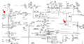
The weighted sum of three ACVS voltages is fed to the delay ramp comparator

