BNC connector with readout ring: Difference between revisions
Jump to navigation
Jump to search
No edit summary |
No edit summary |
||
| Line 6: | Line 6: | ||
The connector of compatible probes, e.g. [[P6056]], includes a contact pin connecting this ring. | The connector of compatible probes, e.g. [[P6056]], includes a contact pin connecting this ring. | ||
A resistor connected to ground encodes the probe attenuation, e.g. 11 kΩ indicates a ×10 probe and 6.8 kΩ a ×100 probe. | A resistor connected to ground encodes the probe attenuation, e.g. 11 kΩ indicates a ×10 probe and 6.8 kΩ a ×100 probe<ref>See [[Media:010-6056-03.pdf|Tektronix P6056/P6057 Manual]]</ref>. | ||
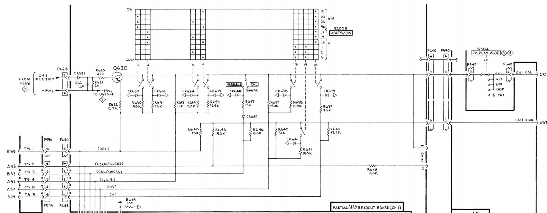
* In most [[7000-series plug-ins]], the ring interfaces with the [[7000 series readout system|readout system]]. The [[Media:Tek-plugin-readout.jpg|plug-in circuit]] uses the shift instructions in time slot 1 to implement the change of range. <br />If the probe includes an Identify switch at the tip, this connects the readout pin directly to ground, encoding the special IDENTIFY instruction in time slot 1. | * In most [[7000-series plug-ins]], the ring interfaces with the [[7000 series readout system|readout system]]. The [[Media:Tek-plugin-readout.jpg|plug-in circuit]] uses the shift instructions in time slot 1 to implement the change of range. <br />If the probe includes an Identify switch at the tip, this connects the readout pin directly to ground, encoding the special IDENTIFY instruction in time slot 1. | ||
| Line 17: | Line 17: | ||
* [http://www.electronics-related.com/sci.electronics.design/thread/116046/readout-pin-on-oscilloscope-probes.php Thread about probe readout details] | * [http://www.electronics-related.com/sci.electronics.design/thread/116046/readout-pin-on-oscilloscope-probes.php Thread about probe readout details] | ||
* [https://www.thingiverse.com/thing:5463077 3D model for replacing the plastic twist-on/pin holder ring on many Tek probes], e.g. [[P6105]] | * [https://www.thingiverse.com/thing:5463077 3D model for replacing the plastic twist-on/pin holder ring on many Tek probes], e.g. [[P6105]] | ||
===References=== | |||
<references /> | |||
[[Category:Probe interfaces]] | [[Category:Probe interfaces]] | ||
[[Category:Introduced in 1969]] | [[Category:Introduced in 1969]] | ||
Revision as of 05:46, 29 July 2023


Many 1970s/1980s Tektronix scopes and plugins have rings around the BNC input sockets that allow the attenuation factor of attached probes to be detected by the scope.
The connector of compatible probes, e.g. P6056, includes a contact pin connecting this ring. A resistor connected to ground encodes the probe attenuation, e.g. 11 kΩ indicates a ×10 probe and 6.8 kΩ a ×100 probe[1].
- In most 7000-series plug-ins, the ring interfaces with the readout system. The plug-in circuit uses the shift instructions in time slot 1 to implement the change of range.
If the probe includes an Identify switch at the tip, this connects the readout pin directly to ground, encoding the special IDENTIFY instruction in time slot 1. - Readout-less 5000-series plug-ins and a number of standalone scopes of the same era, e.g. many of the 400-series scopes such as 464, use the ring to detect a ×10 (but not a ×100) probe, and indicate the correct scale factor using front-panel lamps or LEDs. The 485 also uses the probe ring and utilizes a TEK custom IC 155-0076-00 and three LEDs to indicate ×1, ×10, and ×100 probes.
- 7000-series scopes only display ×1, ×10 and ×100 factors. 11K, TDS, 2400 and later recognize ×1000, ×2, ×5, ×200 and possibly other factors.
- The 7A14 plugin uses the same BNC connector with a ring but the ring serves a different purpose, which is to detect the difference between the P6021 and P6022 probes, and switching in appropriate gain and frequency compensation. The P6021 (or a 131-0750-00 adapter for the P6019) shorts this ring to ground, directly switching three relays connected to −15 V internally.
See also
- 7000 series readout system
- Thread about probe readout details
- 3D model for replacing the plastic twist-on/pin holder ring on many Tek probes, e.g. P6105