C: Difference between revisions
(template) |
No edit summary |
||
| Line 47: | Line 47: | ||
<gallery> | <gallery> | ||
C_early_1.JPG|53C-Plugin´s Front | |||
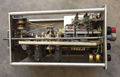
C_early_2.JPG|53C-Plugin´s chassis | |||
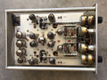
C_early_3.JPG|53C-Plugin´s chassis side | |||
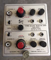
C later 1.JPG|53/54C-Plugin´s front | |||
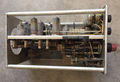
IMG 0949.JPG|53/54C-Plugin´s chassis | |||
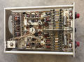
C later 3.JPG|53/54C-Plugin´s chassis bottom | |||
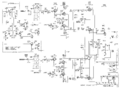
Tek c schem.png | |||
Tek 53-54c 1.jpg|53/54C | |||
Tek 53-54c 2.jpg|53/54C | |||
Tek 53-54c 3.jpg|53/54C | |||
Tek 53-54c 4.jpg|53/54C | |||
Tek 53-54c 5.jpg|53/54C | |||
Tek 53-54c 6.jpg|53/54C | |||
</gallery> | </gallery> | ||
[[Category:500 series plugins]] | [[Category:500 series plugins]] | ||
Revision as of 19:19, 29 October 2017
- Actually, there never was a Type C, but that name is sometimes used as shorthand for the official "Type 53C" and "Type 53/54C" nomenclatures.
The Tektronix Type 53C is a dual-trace plug-in for 500-series scopes. It was introduced along with the 531 and 535 mainframes in 1954. It is very possibly the first dual-trace scope or plugin ever.
Specifications
In the 53x scopes (Tek never documented its performance in the 540's), its bandwidth is 8.5 MHz, and like most letter-series plug-ins, its maximum vertical sensitivity is 50 mV/div. Unlike the Type A and Type B, the Type C had the ability to invert the signal before display.
Type 53C was replaced by Type 53/54C in 1956 when the 541 and 545 were introduced. The Type 53/54C's bandwidth is 24 MHz in those scopes. In 1959 it was replaced by Type CA.
Internals
At 15 tubes, the Type 53/54C and Type CA have the highest tube count of any letter-series plug-in. Each channel consists of a 6AK5 cathode-follower driving a 12AU6 differential pair which drives a 6AU6 differential pair. The two channels converge on a 12AT7 cross-coupled cathode-follower. Four more tubes, a 6AL5 and three 12AT7's, comprise a logic circuit which determines which channel drives the output at any given moment. The options are A, B, CHOPPED, and ALT.
Links
Pictures
-
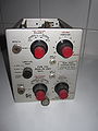
53C-Plugin´s Front
-
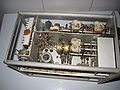
53C-Plugin´s chassis
-
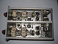
53C-Plugin´s chassis side
-
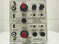
53/54C-Plugin´s front
-

53/54C-Plugin´s chassis
-

53/54C-Plugin´s chassis bottom
-
-
53/54C
-
53/54C
-
53/54C
-
53/54C
-
53/54C
-

53/54C


