Cam switches: Difference between revisions
Jump to navigation
Jump to search
No edit summary |
No edit summary |
||
| Line 10: | Line 10: | ||
==Pictures== | ==Pictures== | ||
<gallery> | <gallery> | ||
Tek 7a19 frontright.jpg|Cam switch in [[7A19]] | Tek 7a19 frontright.jpg | Cam switch in [[7A19]] | ||
Tek 7a19 rearright.jpg|Cam switch in [[7A19]] | Tek 7a19 rearright.jpg | Cam switch in [[7A19]] | ||
Tek 7a19 att sw3.jpg|Cam switch in [[7A19]], contact fingers | Tek 7a19 att sw3.jpg | Cam switch in [[7A19]], contact fingers (isolated from spring lever) | ||
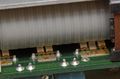
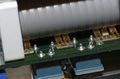
Cam-01.jpg | Cam-01.jpg | Cam switch with contacts on both sides of the PCB ([[7D15]]) | ||
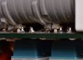
Cam-02.jpg | Cam-02.jpg | 7D15 double-sided switch | ||
Cam-03.jpg | Cam-03.jpg | 7D15 double-sided switch | ||
Cam-04.jpg | 7D15 double-sided switch, bottom-side contacts | |||
Cam-05.jpg | 7D15 double-sided switch, through-board pins | |||
</gallery> | </gallery> | ||
[[Category:Repair issues]] | [[Category:Repair issues]] | ||
Revision as of 03:32, 30 December 2016
Cam switches are used in many Tek instruments, particularly in 7000-series plug-ins, but also in 400-series portable scopes.
The lobes on the rotary cam encode the lookup table of which contacts should be open or closed in each rotational position of the shaft, which is typically rotated by a knob on the front panel of the instrument. A benefit of this design is low parasitics compared to traditional rotary wafer switches.
Maintenance
Pictures
-
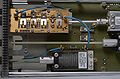
Cam switch in 7A19
-
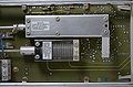
Cam switch in 7A19
-
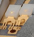
Cam switch in 7A19, contact fingers (isolated from spring lever)
-

Cam switch with contacts on both sides of the PCB (7D15)
-
7D15 double-sided switch
-
7D15 double-sided switch
-

7D15 double-sided switch, bottom-side contacts
-
7D15 double-sided switch, through-board pins


