PS5004: Difference between revisions
(5000) |
No edit summary |
||
| Line 17: | Line 17: | ||
File:Tek ps5004.jpg | File:Tek ps5004.jpg | ||
</gallery> | </gallery> | ||
Revision as of 10:38, 23 October 2015
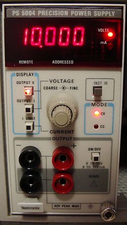
The Tektronix PS5004 is a programmable precision power supply plug-in for the TM5000 system. It operates in TM5003 or TM5006 mainframes. The maximum output power does not change when operated in the TM5006 high power compartment.
The output range is 0 to +20.0000 V, settable in 500 μV steps. Output current can be adjusted from 5 to 300 mA in 5 mA steps. A 4-2/3 digital meter monitors can be selected to monitor the actual output voltage, output current, or current limit setting. Results are displayed on the front panel LED display, and can be read through the GPIB.
The power supply has a basic DC accuracy of 0.01%, better than many 4½ digit DMMs. It can be used as a programmable calibration source for many 3½ digit meter applications. To maintain the precision at the point of use, the outputs have remote sensing inputs. Internal resistors clamp the sensing inputs to the output terminals, allowing the supply to be used with the sensing terminals left open.
The power supply used a unique method of programming the voltage. At the time the instrument was designed, 16 bit DACs using conventional R-2R ladder networks were rare and extremely expensive – more than the target manufacturing cost for the entire instrument. The DAC uses a gated charge transfer technique, and is implemented from discrete components. The output of a negative precision current source is steered either into the summing node of a current to voltage converter, or pulled up to a supply voltage. The switch is driven by a digital logic which forms a constant period, variable pulse width waveform. A digital counter determines the pulse width, with each count representing the weight of a least significant bit. An integrator, followed by a four pole quasi-elliptical filter tuned to the pulse frequency reduce the ripple to less than 100 μV.

