S-6: Difference between revisions
(image) |
No edit summary |
||
| (5 intermediate revisions by the same user not shown) | |||
| Line 1: | Line 1: | ||
{{Plugin Sidebar | | {{Plugin Sidebar 2| | ||
title=Tektronix S-6 | | title=Tektronix S-6 | | ||
summary=Sampling Head | | summary=Sampling Head | | ||
image=Tek-s6-front.jpg | | image=Tek-s6-front.jpg | | ||
caption=S-6 head | | caption=S-6 head | | ||
series= | series={{3S+7S}} | | ||
introduced=1971 | | |||
discontinued=1990 | | |||
manuals= | manuals= | ||
* [http://w140.com/tek_nov1988_s6.pdf Tektronix S-6 Manual (high quality, 1988, PDF)] | * [http://w140.com/tek_nov1988_s6.pdf Tektronix S-6 Manual (high quality, 1988, PDF)] | ||
| Line 13: | Line 15: | ||
It is good practice to leave a termination resistor on the unit when unused to give some protection against electrostatic discharge. | It is good practice to leave a termination resistor on the unit when unused to give some protection against electrostatic discharge. | ||
{{BeginSpecs}} | {{BeginSpecs}} | ||
| Line 30: | Line 30: | ||
* [http://jeroen.web.cern.ch/jeroen/S6/S6.shtml S-6 internal photo and simulation] | * [http://jeroen.web.cern.ch/jeroen/S6/S6.shtml S-6 internal photo and simulation] | ||
* [https://www.circuitsathome.com/measurements/repairing-tektronix-s-6-sampling-head Repairing an S-6 head] (with internal photos) | * [https://www.circuitsathome.com/measurements/repairing-tektronix-s-6-sampling-head Repairing an S-6 head] (with internal photos) | ||
* [http://www.amplifier.cd/Test_Equipment/Tektronix/Tektronix_7000_series_special/7S12.htm S- | * [http://www.amplifier.cd/Test_Equipment/Tektronix/Tektronix_7000_series_special/7S12.htm S-6 @ amplifier.cd 7S12 page] | ||
* http://www.barrytech.com/tektronix/tek7000/ | * [http://www.barrytech.com/tektronix/tek7000/teks6.html S-6 @ barrytech.com] | ||
==Pictures== | ==Pictures== | ||
Revision as of 01:09, 26 July 2015
Template:Plugin Sidebar 2 The Tektronix S-6 Sampling Head plug-in is a 50 Ω feed-through unit with a rise-time of 30 ps and bandwidth of 11.5 GHz. It was introduced in 1971. The S-6 provides two unterminated 50 Ω SMA connections in a loop-through configuration as is convenient for TDR applications.
It is good practice to leave a termination resistor on the unit when unused to give some protection against electrostatic discharge.
Key Specifications
| Rise time | 30 ps |
|---|---|
| Bandwidth | 11.5 GHz |
| Input impedance | 50 Ω (unterminated!) |
| Noise | < 5 mV of noise |
| Features |
|
Links
- S-6 internal photo and simulation
- Repairing an S-6 head (with internal photos)
- S-6 @ amplifier.cd 7S12 page
- S-6 @ barrytech.com
Pictures
-
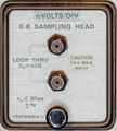
S-6 front
-
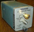
S-6, entire plugin
-
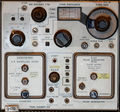
S-6 sampling head and S-52 pulse generator head in a 7S12 TDR/Sampler plugin


Measurements
-
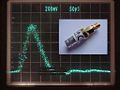
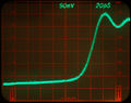
Impulse taken with S6 sampling head. Every dot is equivalent to one sample taken, and combined on the CRT with a rate of app. 100 Hz. Bright dots are newer than dimmed ones.
-
Incident pulse from an S-52 (nom. < 25 ps) displayed by an S-6 head (nom. < 30 ps), both installed in a 7S12. Displayed rise time ~35 ps confirms spec.
-
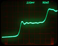
"Self Portrait" of an S-6: A pulse reflected on the unterminated "through" path (approx. 120 ps one way)


