TDS540: Difference between revisions
Jump to navigation
Jump to search
No edit summary |
No edit summary |
||
| (11 intermediate revisions by 3 users not shown) | |||
| Line 7: | Line 7: | ||
summary=500 MHz, 1 GS/s digital scope | | summary=500 MHz, 1 GS/s digital scope | | ||
manuals= | manuals= | ||
* [ | * [[Media:070-9382-01.pdf|TDS500B Quick Reference]] (PDF) | ||
* [ | * [[Media:070-9719-00.pdf|TDS500B User Manual]] (PDF) | ||
* [[Media:070-9721-02.pdf|TDS500B Service Manual]] (PDF) | |||
* [[Media:070-9384-01.pdf|TDS500B Performance Verification and Specifications]] (PDF) | |||
* [[Media:071-0130-00.pdf|TDS500D User Manual]] (PDF) | |||
* [[Media:071-0627-02.pdf|TDS500D Service Manual]] (PDF) | |||
* [[Media:070-8709-07.pdf|TDS Family Digitizing Oscilloscopes − Programmer Manual]] (PDF) | |||
* [[Media:TB-9-6625-2320-35.pdf|TB-9-6625-2320-35 Calibration procedure for TDS540B]] | * [[Media:TB-9-6625-2320-35.pdf|TB-9-6625-2320-35 Calibration procedure for TDS540B]] | ||
* [ | * [[Media:TDS540 Schematics.pdf|Tektronix TDS540 Schematics (PDF)]] | ||
}} | }} | ||
The '''Tektronix TDS540''' is a 500 MHz, 1 GS/s quad-channel digital scope introduced in 1992. | The '''Tektronix TDS540''' is a 500 MHz, 1 GS/s quad-channel digital scope introduced in 1992. | ||
{{ | The TDS540 uses an amplifier IC, U1000, U1200, U1300, and U1400, part number [[155-0378-00]], that is closely related to the [[M377]]. | ||
Common failure on early TDS-Familiy: bad SMD Capacitor. | |||
{{BeginSpecs}} | |||
{{Spec | Bandwidth | 500 MHz }} | |||
{{Spec | Rise time | 700 ps }} | |||
{{Spec | Sample rate | 1 GS/s (only 1 ch ) / 500 MS/s (only 2 ch) / 250 MS/s (all ch) }} | |||
{{Spec | Time base | 500 ps/Div to 10 s/Div }} | |||
{{Spec | Deflection | 2 mV/Div to 200 mV/Div (Opt. 1D: 1 mV/Div to 100 mV/Div) }} | |||
{{Spec | Resolution | 8 bits / 12 bits (HI-RES Mode) }} | |||
{{Spec | Record length | 500 to 15 k points ( Opt. 1M: 50 k points) }} | |||
{{Spec | Input impedance | 1 MΩ / 50 Ω }} | |||
{{Spec | Interface | GPIB standard }} | |||
{{Spec | Options 13 | | |||
* Centronics interface | |||
* RS-232 interface | |||
}} | |||
{{EndSpecs}} | |||
==Options== | |||
*05 - Video Trigger | |||
*13 - RS-232/CENTRONICS HARDCOPY INTERFACE. | |||
*1K - [[K420]] Oscilloscope Cart without power strip | |||
*1M - 50k Memory Length | |||
*1R - Rackmount | |||
*23 - Add two each [[P6205]] Active Probes | |||
*25 - Add [[P6563A]], four SMD probes | |||
*2F - ADVANCED DSP MATH | |||
==Pictures== | ==Pictures== | ||
| Line 21: | Line 55: | ||
tds540-2.jpg | tds540-2.jpg | ||
tds540-3.jpg | tds540-3.jpg | ||
TDS540_A10.JPG |SMD caps recapped Acquisition-Board "A10" | |||
</gallery> | </gallery> | ||
[[Category: | |||
== Part numbers of included PCB by TDS540 == | |||
{| class="wikitable" | |||
|- | |||
! Part No | |||
! Description | |||
! Modul numbers | |||
|- | |||
| 672-1476-0x|| Acquisition board || A10 | |||
|- | |||
| 672-2045-0x|| Acquisition board (1M Option) || A10 | |||
|- | |||
| 671-1477-01/02 || DRAM/CPU/Display board (1M Option)|| A11 | |||
|- | |||
| 671-2002-01/02 || DRAM/CPU/Display board || A11 | |||
|- | |||
| 614-0890-00 || Front panel assembly || A12 | |||
|- | |||
| 614-0896-00/01 || Front panel assembly || A12 | |||
|- | |||
| 671-1701-00/01 || Firmware board || A13 | |||
|- | |||
| 671-1568-00|| D1 Bus|| A14 | |||
|- | |||
| 119-4092-0x|| Attenuator assembly|| A15 | |||
|- | |||
| 119-3371-0x|| Power supply unit || A16 | |||
|- | |||
| 119-4415-0x|| Power supply unit || A16 | |||
|- | |||
| 640-0071-00/01|| CRT Display assembly|| A20 | |||
|- | |||
|} | |||
[[Category:TDS500 series scopes]] | |||
Revision as of 07:05, 19 May 2019

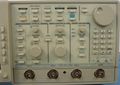
The Tektronix TDS540 is a 500 MHz, 1 GS/s quad-channel digital scope introduced in 1992.
The TDS540 uses an amplifier IC, U1000, U1200, U1300, and U1400, part number 155-0378-00, that is closely related to the M377.
Common failure on early TDS-Familiy: bad SMD Capacitor.
Key Specifications
| Bandwidth | 500 MHz |
|---|---|
| Rise time | 700 ps |
| Sample rate | 1 GS/s (only 1 ch ) / 500 MS/s (only 2 ch) / 250 MS/s (all ch) |
| Time base | 500 ps/Div to 10 s/Div |
| Deflection | 2 mV/Div to 200 mV/Div (Opt. 1D: 1 mV/Div to 100 mV/Div) |
| Resolution | 8 bits / 12 bits (HI-RES Mode) |
| Record length | 500 to 15 k points ( Opt. 1M: 50 k points) |
| Input impedance | 1 MΩ / 50 Ω |
| Interface | GPIB standard |
| Options 13 |
|
Options
- 05 - Video Trigger
- 13 - RS-232/CENTRONICS HARDCOPY INTERFACE.
- 1K - K420 Oscilloscope Cart without power strip
- 1M - 50k Memory Length
- 1R - Rackmount
- 23 - Add two each P6205 Active Probes
- 25 - Add P6563A, four SMD probes
- 2F - ADVANCED DSP MATH
Pictures
-

-
-

-
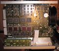
SMD caps recapped Acquisition-Board "A10"


Part numbers of included PCB by TDS540
| Part No | Description | Modul numbers |
|---|---|---|
| 672-1476-0x | Acquisition board | A10 |
| 672-2045-0x | Acquisition board (1M Option) | A10 |
| 671-1477-01/02 | DRAM/CPU/Display board (1M Option) | A11 |
| 671-2002-01/02 | DRAM/CPU/Display board | A11 |
| 614-0890-00 | Front panel assembly | A12 |
| 614-0896-00/01 | Front panel assembly | A12 |
| 671-1701-00/01 | Firmware board | A13 |
| 671-1568-00 | D1 Bus | A14 |
| 119-4092-0x | Attenuator assembly | A15 |
| 119-3371-0x | Power supply unit | A16 |
| 119-4415-0x | Power supply unit | A16 |
| 640-0071-00/01 | CRT Display assembly | A20 |