WM490: Difference between revisions
No edit summary |
No edit summary |
||
| (9 intermediate revisions by 4 users not shown) | |||
| Line 1: | Line 1: | ||
{{ | {{Instrument Sidebar | ||
|manufacturer=Tektronix | |||
summary=Waveguide | |model=WM490 | ||
image=Tek_WM490.jpg | | |class=Accessory | ||
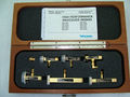
caption=Tektronix WM490 | | |summary=Waveguide mixer | ||
introduced=1982 | | |image=Tek_WM490.jpg | ||
discontinued=1990 | | |caption=Tektronix WM490 | ||
manuals= | |introduced=1982 | ||
* [[Media: 070-3731-01.pdf | 070-3731-01 | |discontinued=1990 | ||
* [[Media:Tek_WM490_Catalog_Spec_1982.pdf| Tektronix WM490 Introduction Spec | |manuals= | ||
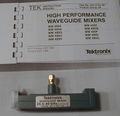
* [[Media:Tek_WM490_Catalog_Spec_1989.pdf| Tektronix WM490 Final Spec | * [[Media:062-4566-00.pdf|High Performance Waveguide Mixers for the 492 and 7L18]] | ||
* [[Media: 070-3731-01.pdf | 070-3731-01 WM490 Instruction Manual]] (OCR) | |||
* [[Media:Tek_WM490_Catalog_Spec_1982.pdf| Tektronix WM490 Introduction Spec]] | |||
* [[Media:Tek_WM490_Catalog_Spec_1989.pdf| Tektronix WM490 Final Spec]] | |||
}} | }} | ||
The '''Tektronix WM490''' is a series of waveguide mixers for the [[7L18]] and the [[49X_Series_Comparison|49X-series, 475X-series, and 279X-series spectrum analyzers]], e.g., the [[492]]. The mixers directly connect to the [[7L18]] using an SMA cable, while the stand alone spectrum analyzers require an additional [[015-0385-00]] diplexer to merge the LO, IF and bias signals in a single cable. | |||
The '''Tektronix WM490''' is a series of waveguide mixers for | |||
A waveguide is a structure which guides energy waves, such as electromagnetic waves or sound waves. Waveguides are metallic lines, similar in fashion to transmission lines, which are used at microwave frequencies. Unlike coaxial cable which is also a transmission line, there is no center conductor within the waveguide. Signals propagate within the confines of the metallic walls that act as boundaries. The signal propagation is confined by total internal reflection from the walls of the waveguide. | A waveguide is a structure which guides energy waves, such as electromagnetic waves or sound waves. Waveguides are metallic lines, similar in fashion to transmission lines, which are used at microwave frequencies. Unlike coaxial cable which is also a transmission line, there is no center conductor within the waveguide. Signals propagate within the confines of the metallic walls that act as boundaries. The signal propagation is confined by total internal reflection from the walls of the waveguide. | ||
| Line 28: | Line 30: | ||
|- | |- | ||
! scope="col"| Model No. | ! scope="col"| Model No. | ||
! scope="col"| Old Model No. | |||
! scope="col"| Band Desig. | ! scope="col"| Band Desig. | ||
! scope="col"| Freq Range (GHz) | ! scope="col"| Freq Range (GHz) | ||
| Line 34: | Line 37: | ||
! scope="col"| U-Type Flanges | ! scope="col"| U-Type Flanges | ||
|- style="text-align:center;" | |- style="text-align:center;" | ||
|WM490K || K || 18.8 to 26.5 || -100 || WR-42 || UG-595/U | |WM490K || 016-0631-01 || K || 18.8 to 26.5 || -100 || WR-42 || UG-595/U | ||
|- style="text-align:center;" | |- style="text-align:center;" | ||
|WM490A || A || 26.5 to 40 || -95 || WR-28 || UG-599/U | |WM490A || 016-0632-01 ||A || 26.5 to 40 || -95 || WR-28 || UG-599/U | ||
|- style="text-align:center;" | |- style="text-align:center;" | ||
|WM490Q || Q || 33 to 50 || -95 || WR-22 || UG-383/U | |WM490Q || || Q || 33 to 50 || -95 || WR-22 || UG-383/U | ||
|- style="text-align:center;" | |- style="text-align:center;" | ||
|WM490U || U || 40 to 60 || -95 || WR-19 || UG-383/U-M | |WM490U || 016-0634-01 ||U || 40 to 60 || -95 || WR-19 || UG-383/U-M | ||
|- style="text-align:center;" | |- style="text-align:center;" | ||
|WM490V || V || 50 to 75 || -95 at 50 GHz<br/>-90 at 75 GHz typ. || WR-15 || UG-385/U | |WM490V || || V || 50 to 75 || -95 at 50 GHz<br/>-90 at 75 GHz typ. || WR-15 || UG-385/U | ||
|- style="text-align:center;" | |- style="text-align:center;" | ||
|WM490E || E || 60 to 90 || -95 at 60 GHz<br/>-90 at 90 GHz typ. || WR-12 || UG-387/U | |WM490E || 016-0664-00 ||E || 60 to 90 || -95 at 60 GHz<br/>-90 at 90 GHz typ. || WR-12 || UG-387/U | ||
|- style="text-align:center;" | |- style="text-align:center;" | ||
|WM490W || W || 75 to 110 || -90 at 75 GHz<br/>-80 at 110 GHz typ. || WR-10 || UG-387/U-M | |WM490W || || W || 75 to 110 || -90 at 75 GHz<br/>-80 at 110 GHz typ. || WR-10 || UG-387/U-M | ||
|- style="text-align:center;" | |- style="text-align:center;" | ||
|WM490F || F || 90 to 140 || -85 at 90 GHz<br/>-75 at 140 GHz typ. || WR-08 || UG-387/U-M | |WM490F ||016-0665-00 || F || 90 to 140 || -85 at 90 GHz<br/>-75 at 140 GHz typ. || WR-08 || UG-387/U-M | ||
|- style="text-align:center;" | |- style="text-align:center;" | ||
|WM490D || D || 110 to 170 || -80 at 110 GHz<br/>-70 at 170 GHz typ. || WR-06 || UG-387/U-M | |WM490D || || D || 110 to 170 || -80 at 110 GHz<br/>-70 at 170 GHz typ. || WR-06 || UG-387/U-M | ||
|- style="text-align:center;" | |- style="text-align:center;" | ||
|WM490G || G || 140 to 220 || -75 at 140 GHz<br/>-65 at 220 GHz typ. || WR-05 || UG-387/U-M | |WM490G || || G || 140 to 220 || -75 at 140 GHz<br/>-65 at 220 GHz typ. || WR-05 || UG-387/U-M | ||
|- style="text-align:center;" | |- style="text-align:center;" | ||
|119-1728-00<br/>G-J Band flange transition || J || 220 to 325 || -65 at 220 GHz<br/>-50 at 325 GHz typ. || WR-05<br/>WR-03 || 74-003<br/>74-005 | |119-1728-00<br/>G-J Band flange transition || || J || 220 to 325 || -65 at 220 GHz<br/>-50 at 325 GHz typ. || WR-05<br/>WR-03 || 74-003<br/>74-005 | ||
|} | |} | ||
| Line 62: | Line 65: | ||
* The waveguide height is half the waveguide width. | * The waveguide height is half the waveguide width. | ||
* The Electronic Industries Alliance (EIA) is the body that defined the WR designations for standard rectangular waveguides. | * The Electronic Industries Alliance (EIA) is the body that defined the WR designations for standard rectangular waveguides. | ||
* A set of two WG mixers covering 18-40 GHz is called 016-0662-00. | |||
* A set of three WG mixers covering 18-60 GHz is called 016-0657-00. | |||
==Links== | ==Links== | ||
* [http://www.nitehawk.com/k6jey/harmonic_mixers.pptx Harmonic Mixers for Spectrum Analyzers y K6JEY] | * [http://www.nitehawk.com/k6jey/harmonic_mixers.pptx Harmonic Mixers for Spectrum Analyzers y K6JEY] | ||
* [[Media:VOL_10_Waveguide_Handbook.pdf | M.I.T. Radiation Laboratory Series, Waveguide Handbook, N. Marcuvitz, 1951 | * [[Media:VOL_10_Waveguide_Handbook.pdf | M.I.T. Radiation Laboratory Series, Waveguide Handbook, N. Marcuvitz, 1951]] | ||
* [ | * [[wikipedia:Waveguide_(electromagnetism)#Waveguide_in_practice|Waveguide (electromagnetism)]] / [[wikipedia:Waveguide_flange|Waveguide flange]] @ Wikipedia | ||
{{Documents|Link=WM490}} | |||
==Pictures== | ==Pictures== | ||
| Line 84: | Line 88: | ||
Tek wm490 11.jpg | Tek wm490 11.jpg | ||
Tek wm490 12.jpg | Tek wm490 12.jpg | ||
Tek 016-0632-01.jpg|016-0632-01 | |||
Tek 016-0632-00.jpg|016-0632-00 | |||
Tek wm490 specs in 494.png|Specs of WM490 Mixers with [[494]] | Tek wm490 specs in 494.png|Specs of WM490 Mixers with [[494]] | ||
</gallery> | </gallery> | ||
Latest revision as of 03:11, 2 April 2024

The Tektronix WM490 is a series of waveguide mixers for the 7L18 and the 49X-series, 475X-series, and 279X-series spectrum analyzers, e.g., the 492. The mixers directly connect to the 7L18 using an SMA cable, while the stand alone spectrum analyzers require an additional 015-0385-00 diplexer to merge the LO, IF and bias signals in a single cable.
A waveguide is a structure which guides energy waves, such as electromagnetic waves or sound waves. Waveguides are metallic lines, similar in fashion to transmission lines, which are used at microwave frequencies. Unlike coaxial cable which is also a transmission line, there is no center conductor within the waveguide. Signals propagate within the confines of the metallic walls that act as boundaries. The signal propagation is confined by total internal reflection from the walls of the waveguide.
As described in "Spectrum Analysis Utilizing Waveguide Mixers" the Tektronix Application Note 26W5390 states that whether a measurement is made at audio frequencies or millimeter wavelengths, the spectrum analyzer is used to measure amplitude vs. frequency. Typical measurements include spectral energy distribution or signature of the energy source. This can be as simple as measuring harmonic levels of a continuous wave source to a more complicated occupied bandwidth measurement of a digital microwave transmission system.
Actual spectrum analyzer measurements at millimeter wavelengths differ from lower frequency measurements in the transition from coaxial cables to waveguides. Most spectrum analyzers have an internal mixer upper frequency limit of 21 to 22 GHz, and utilize a type "N" RF input connector.
When the requirement measurement is above 22 GHz, some type of external mixing is required. Current techniques utilize harmonics of the spectrum analyzer first sweeping LO and an external harmonic waveguide mixer covering the designer frequency range. The mixers extend the frequency range of measurement up to as high as 325 GHz. Each mixer covers a separate frequency range, typically about two thirds of an octave.
Note: The MIL-F-39000/3C which describes flanges for double-ridge waveguide was cancelled without replacement on January 20, 2009.
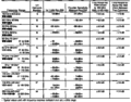
| Model No. | Old Model No. | Band Desig. | Freq Range (GHz) | Sensitivity (dBm) |
Waveguide (EIA) | U-Type Flanges |
|---|---|---|---|---|---|---|
| WM490K | 016-0631-01 | K | 18.8 to 26.5 | -100 | WR-42 | UG-595/U |
| WM490A | 016-0632-01 | A | 26.5 to 40 | -95 | WR-28 | UG-599/U |
| WM490Q | Q | 33 to 50 | -95 | WR-22 | UG-383/U | |
| WM490U | 016-0634-01 | U | 40 to 60 | -95 | WR-19 | UG-383/U-M |
| WM490V | V | 50 to 75 | -95 at 50 GHz -90 at 75 GHz typ. |
WR-15 | UG-385/U | |
| WM490E | 016-0664-00 | E | 60 to 90 | -95 at 60 GHz -90 at 90 GHz typ. |
WR-12 | UG-387/U |
| WM490W | W | 75 to 110 | -90 at 75 GHz -80 at 110 GHz typ. |
WR-10 | UG-387/U-M | |
| WM490F | 016-0665-00 | F | 90 to 140 | -85 at 90 GHz -75 at 140 GHz typ. |
WR-08 | UG-387/U-M |
| WM490D | D | 110 to 170 | -80 at 110 GHz -70 at 170 GHz typ. |
WR-06 | UG-387/U-M | |
| WM490G | G | 140 to 220 | -75 at 140 GHz -65 at 220 GHz typ. |
WR-05 | UG-387/U-M | |
| 119-1728-00 G-J Band flange transition |
J | 220 to 325 | -65 at 220 GHz -50 at 325 GHz typ. |
WR-05 WR-03 |
74-003 74-005 |
Notes:
- All mixers are equipped with standard UG-XXX/U type flanges as indicated. Flange adapters to standard MIL-F-3022 type flanges are provided in F, D, and G bands at no additional charge.
- The waveguide name WR stands for waveguide rectangular, and the number is the inner dimension width of the waveguide in hundredths of an inch (0.01 inch = 0.254 mm) rounded to the nearest hundredth of an inch.
- The waveguide height is half the waveguide width.
- The Electronic Industries Alliance (EIA) is the body that defined the WR designations for standard rectangular waveguides.
- A set of two WG mixers covering 18-40 GHz is called 016-0662-00.
- A set of three WG mixers covering 18-60 GHz is called 016-0657-00.
Links
- Harmonic Mixers for Spectrum Analyzers y K6JEY
- M.I.T. Radiation Laboratory Series, Waveguide Handbook, N. Marcuvitz, 1951
- Waveguide (electromagnetism) / Waveguide flange @ Wikipedia
Documents Referencing WM490
| Document | Class | Title | Authors | Year | Links |
|---|---|---|---|---|---|
| 26W-5390.pdf | Application Note | Spectrum Analysis utilizing Waveguide Mixers | Bob Alm • Len Garrett | 1983 | WM490 |
Pictures
-
-

-

-

-

-

-

-

-

-

-

-
-
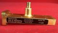
016-0632-01
-
016-0632-00
-
Specs of WM490 Mixers with 494


