2797

The Tektronix 2797 is a spectrum analyzer with a frequency range of 100 Hz to 7.1 GHz and 10 Hz minimum resolution bandwidth, with digital storage.
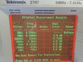
Non-volatile memory (NVRAM) stores up to 9 separate waveforms with their readouts and markers, and up to 10 different front-panel control setups.
The single and delta markers provide direct readout of frequency and amplitude information of any point along any displayed trace, or indicate the relative (delta) frequency and amplitude information between any two points along any displayed trace, or between traces.
The instrument can selectively count one particular signal out of several that may be present at its input.
Key Specifications
| Frequency | 100 Hz to 7.1 GHz |
|---|---|
| Frequency Span | 100 Hz to 4 GHz (plus 0 Hz and MAX) |
| Resolution Bandwidth | 6 dB bandwidths from 10 Hz to 3 MHz |
| RF Input impedance | 50 Ω |
| Maximum Safe Input Power | 1 Watt (+30 dBm) CW, or 75 W peak, 1 µs, 0.1% duty factor |
| RF Attenuator | 0 dB to 60 dB, 10 dB steps |
| Reference Level | −117 dBm to +30 dBm |
| LO Output | (2 to 6 GHz) 1st LO: +6 dBm to +20 dBm; 2nd LO: −12 dBm to +5 dBm |
| Sweep Speed | 100 s to 200 µs in 1, 2, 5 sequence |
| Video Bandwidth | 0.3 Hz to 30 kHz |
| Triggering Modes | Free Run, Line, Video, Single, Ext |
| Displayed Average Noise | −75 dBm to −130 dBm |
| Display Dynamic Range | 90 dB |
| Dynamic Range | 130 dBm (Compression to noise) |
| Included Accessories | Operator’s Manual; Programmer’s Manual; 6-ft, 50 Ω coaxial cable, N-N; 18-inch, 50 Ω coaxial cable, BNC-BNC; N male to BNC female adapter; rear connector shield; power cord and spare fuses; CRT filter set consisting of amber and gray light filters plus mesh filter |
| Weight | 20.8 kg (45 lbs) |
| Power | 90 − 132 VAC, 47 – 63 Hz, 210 W max; 180 – 250 VAC, 47 – 63 Hz |
| Additional Features |
|
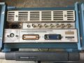
| Front Panel Inputs/Outputs |
RF INPUT 50 Ω (N connector); 1ST LO OUTPUT (SMA connector); 2ND LO OUTPUT (SMA connector); CAL OUT (BNC connector, 100 MHz ±10 Hz, −20 dBm ±0.3 dB) |
| Rear Panel Inputs/Outputs |
|
Options
- Opt. 2: Precision Frequency Reference
- Opt. 23: GRASP software, PC2A interface, GPIB cable
- Opt. 30: Rackmount with handles for 19 in. rack
- Opt. 39: Non-lithium batteries for battery-backed memory
- Opt. 42: Replaces MARKER/VIDEO input port on the rear panel with a 110 MHz IF output port that provides a 3 dB signal bandwidth ≥4.5 MHz
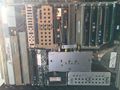
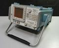
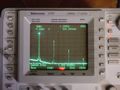
Pictures
-
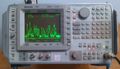
Provided with permission from RadioMuseum.org
-
-
-
-
-

-
-
-
-