S: Difference between revisions
No edit summary |
No edit summary |
||
| Line 10: | Line 10: | ||
* [http://w140.com/kurt/tektronix_type_s.pdf Type S manual] | * [http://w140.com/kurt/tektronix_type_s.pdf Type S manual] | ||
* [http://w140.com/kurt/tek_type_s_schematics.pdf Type S schematics only] | * [http://w140.com/kurt/tek_type_s_schematics.pdf Type S schematics only] | ||
* [http://w140.com/tek_fcp/tek_type_s_factory_cal_proc.pdf Type S factory calibration procedure] | <!-- * [http://w140.com/tek_fcp/tek_type_s_factory_cal_proc.pdf Type S factory calibration procedure] --> | ||
* [[Media:tek_type_s_fcp.pdf|Tektronix Type S factory calibration procedure (PDF, OCR)]] | * [[Media:tek_type_s_fcp.pdf|Tektronix Type S factory calibration procedure (PDF, OCR)]] | ||
}} | }} | ||
Revision as of 15:23, 14 October 2018
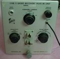
Template:Plugin Sidebar 2 The Tektronix Type S is a plug-in for measuring semiconductor diode recovery characteristics. It fits in 500-series scopes. It can be thought of as having two parts: a stimulus subsystem and a measurement subsystem. The stimulus comes from mercury switch that drives a 6GM8/ECC86 tube that operates in a current-steering mode. The measurement subsystem is a wideband amplifier that converts the single-ended voltage on the diode under test to the differential signal that the oscilloscope mainframe takes. One terminal of the diode is grounded.
Measurements with the Type S are typically made by applying a current step to the diode while observing the voltage across the diode.
The Type S was introduced in 1960 and produced through 1966.
Specifications
please add
Pictures
-
-
Front
-
Chassis
-
Chassis bottom
-
Mercury switch


