360: Difference between revisions
No edit summary |
No edit summary |
||
| Line 9: | Line 9: | ||
* [http://bama.edebris.com/download/tek/160/tek%20160.pdf Tektronix 160 Series Manual (PDF)] | * [http://bama.edebris.com/download/tek/160/tek%20160.pdf Tektronix 160 Series Manual (PDF)] | ||
* [http://w140.com/tek_360_160_irb.pdf Tektronix 160-series Instrument Reference Book (PDF, OCR)] | * [http://w140.com/tek_360_160_irb.pdf Tektronix 160-series Instrument Reference Book (PDF, OCR)] | ||
* [[Media:Tek 360 fcp.pdf|Tektroni 360 Factory Calibration Procedure (PDF, OCR)]] | |||
}} | }} | ||
Revision as of 05:31, 4 May 2021

The Tektronix Type 360 is the "indicator unit" of the 160 series modular scope system.
It contains a 3WP CRT, vertical amplifier, horizontal amplifier, and
HV CRT circuit. It does not contain the low-voltage power supply, which is
a separate component in the 160 system.
Internals
Vertical Signal Path
The vertical signal path starts with a switched compensated attenuator, followed by a 6AU6 differential amplifier stage, followed by a second 6AU6 differential stage.
Horizontal Signal Path
The horizontal amplifier uses a 6AN8 common-cathode gain stage followed by a 6AU6 common-cathode amplifier as a phase splitter to differentially drive the CRT horizontal deflection plates.
CRT Circuit
The CRT circuit in the Type 360 uses a 6AQ5-based power oscillator to drive two 5642 high-voltage rectifier tubes, one for the CRT grid voltage, and one for the CRT cathode voltage. The high-voltage regulator feedback amplifier is made from two cascaded common-cathode amplifiers, each made from one half of a 12AT7 dual triode.
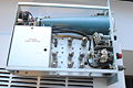
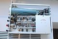
Mechanical
Open-frame construction allows the 360 to operate without fan cooling. Some 360s are made using printed circuit boards. Others are made using the ceramic wiring strip style that is more typical of 1950s and 1960s Tektronix construction.
Pictures
-

360 front view
-
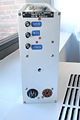
The BNC connectors are a modification.
-
-
-
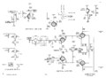
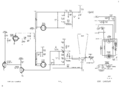
Amplifiers schematic
-
CRT circuit


