4S1: Difference between revisions
No edit summary |
No edit summary |
||
| Line 11: | Line 11: | ||
is called "A vert/B horiz". This mode is used in conjunction with | is called "A vert/B horiz". This mode is used in conjunction with | ||
an X-Y mode switch on the panel of the 661. | an X-Y mode switch on the panel of the 661. | ||
* [http://w140.com/kurt/4s1.pdf 4S1 manual without schematics] | |||
* [http://w140.com/kurt/4s1/ 4S1 schematics] | |||
<gallery> | |||
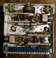
Image:4s1_top.jpg|top view of 4S1 | |||
Image:4s1_timing_pulse_connection.jpg|Coaxial interconnect from timing plug-in goes through the mainframe, into the 4S1, and ends here, at the sampler. | |||
Image:4s1_sampling_bridge.jpg|This is the sampler. The GaAs sampling diodes are arranged in a diamond shape and are directly connected to the socket from the delay line. | |||
Image:4s1_delay_connection.jpg|The delay line is a coil of coax going from the trigger pickoff to the sampler. | |||
</gallery> | |||
Revision as of 19:09, 28 April 2010
The Tektronix Type 4S1 is a dual-trace sampling unit for the 661. Each channel has a trigger pickoff, a delay line, and a sampler. The sampling pulses for each channel are generated by a step recovery diode are are fed to a sampling bridge made with of four GaAs diodes. These diodes are fragile and exact replacements are hard to find. People have improvised replacements using modern integrated Schottky diodes such as those in HP/Agilent's HSMS-28x series. The 4S1 has a dual-trace mode, where the A waveform and the B waveform are both displayed in the time domain at the same time with a single trigger source and a single equivalent-time sweep rate. Another mode is called "A vert/B horiz". This mode is used in conjunction with an X-Y mode switch on the panel of the 661.
-
top view of 4S1
-
Coaxial interconnect from timing plug-in goes through the mainframe, into the 4S1, and ends here, at the sampler.
-
This is the sampler. The GaAs sampling diodes are arranged in a diamond shape and are directly connected to the socket from the delay line.
-
The delay line is a coil of coax going from the trigger pickoff to the sampler.


