WP1000AF: Difference between revisions
No edit summary |
(Minor corrections) |
||
| Line 14: | Line 14: | ||
* [[Media:061-1742-00.pdf | Tektronix 7A16A Mod 515D Manual]] | * [[Media:061-1742-00.pdf | Tektronix 7A16A Mod 515D Manual]] | ||
}} | }} | ||
The '''Tektronix WP1000AF''' [[SPS|Signal Processing System]] is a bundle of a [[P7001|DPO]], two [[7A16A]] vertical and two [[7B71]] horizontal plugins. All components have additional modifications (Mod 515C or -D), which | The '''Tektronix WP1000AF''' [[SPS|Signal Processing System]] is a bundle of a [[P7001|DPO]], two [[7A16A]] vertical plugins and two [[7B71]] horizontal plugins. All components have additional modifications (Mod 515C or -D), which allow an external computer to control some of the front panel settings. The National Stock Number ([[NSN]]) for this bundle is 6625-01-034-4833. | ||
===Parts of the WP1000AF bundle=== | ===Parts of the WP1000AF bundle=== | ||
| Line 54: | Line 54: | ||
The 7704A Mod 515C adds the ability to remotely operate the vertical, horizontal and triggering modes of the mainframe. Additional connectors on the rear are directly connected to the plugin-compartments to allow remote operations for the plugins. | The 7704A Mod 515C adds the ability to remotely operate the vertical, horizontal and triggering modes of the mainframe. Additional connectors on the rear are directly connected to the plugin-compartments to allow remote operations for the plugins. | ||
Pinout of the remote connector for the Mainframe | ====Pinout of the remote connector for the Mainframe==== | ||
{| class="wikitable" | {| class="wikitable" | ||
| Line 103: | Line 103: | ||
Tek_wp1000af_remote_rear.jpg | The additional connectors for remote control (rear view) | Tek_wp1000af_remote_rear.jpg | The additional connectors for remote control (rear view) | ||
Tek_wp1000af_replacement_connectors.jpg | Replacements for the remote control connectors are still available in 2024 | Tek_wp1000af_replacement_connectors.jpg | Replacements for the remote control connectors are still available in 2024 | ||
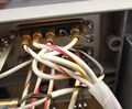
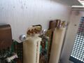
Tek_wp1000af_powersuppply.jpeg | The switch to turn off the control illumination was removed.The | Tek_wp1000af_powersuppply.jpeg | The switch to turn off the control illumination was removed.The Mod 515C needs a permanent 5V supply. | ||
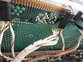
Tek_wp1000af_brd_pwrsupply.jpg | Additional connector board on the power supply | Tek_wp1000af_brd_pwrsupply.jpg | Additional connector board on the power supply | ||
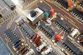
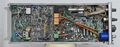
Tek_wp1000af_allboards_mainframe.jpg | Most boards of the | Tek_wp1000af_allboards_mainframe.jpg | Most boards of the Mod 515C modification | ||
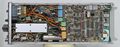
Tek_wp1000af_boards.jpeg | Overview on the additional boards in the lower section of the mainframe | Tek_wp1000af_boards.jpeg | Overview on the additional boards in the lower section of the mainframe | ||
Tek_wp1000af_mode_switches.jpg | The modified mode switches. | Tek_wp1000af_mode_switches.jpg | The modified mode switches. | ||
Tek_wp1000af_horzmode_top.jpg | | Tek_wp1000af_horzmode_top.jpg | Mod 515C horizontal mode switch assembly. The lights work independently from the switches. | ||
Tek_wp1000af_horzmode_bottom.jpg | Mod 515C horizontal mode switch assembly. The lights work independently from the switches. | Tek_wp1000af_horzmode_bottom.jpg | Mod 515C horizontal mode switch assembly. The lights work independently from the switches. | ||
Tek_wp1000af_vertmode_top.jpg | Mod 515C vertical mode switch assembly. The lights work independently from the switches. | Tek_wp1000af_vertmode_top.jpg | Mod 515C vertical mode switch assembly. The lights work independently from the switches. | ||
| Line 136: | Line 136: | ||
The 7A16A Mod 515D adds the ability to remotely operate the Bandwith, Polarity and Position functions of the plugin. | The 7A16A Mod 515D adds the ability to remotely operate the Bandwith, Polarity and Position functions of the plugin. | ||
Pinout of the remote connectors for the vertical plugins | ====Pinout of the remote connectors for the vertical plugins==== | ||
{| class="wikitable" | {| class="wikitable" | ||
| Line 187: | Line 187: | ||
The 7B71 Mod 515C adds the ability to remotely operate the triggering level, the position & delay time, the magnifier setting and the trigger-modes. | The 7B71 Mod 515C adds the ability to remotely operate the triggering level, the position & delay time, the magnifier setting and the trigger-modes. | ||
The | The modified 7B71 timebase can be configured as a delaying or as a delayed timebase. | ||
Pinout of the remote connectors for the horizontal plugins | ====Pinout of the remote connectors for the horizontal plugins==== | ||
{| class="wikitable" | {| class="wikitable" | ||
| Line 289: | Line 289: | ||
===Field of Application=== | ===Field of Application=== | ||
Some | Some details of the modification indicate that the WP1000AF system was developed either specifically for or in close consultation with Honeywell. Honeywell did some additional, but minor modifications to the system. The feet were modified so that the device could be fixed in place. They also added a cable tie holder and a tag to the back of the unit. The result got the Honeywell part-number 10066273-101 and the NSN number 6625-01-060-4390. The pictures on this page show such a device. Honeywell most likely used one of their own type of computer systems to control the DPO. | ||
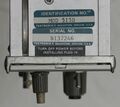
The contractors name and the contract number (see picture below) indicate that this specific | The contractors name and the contract number (see picture below) indicate that this specific instrument was involved in the development of the F15 aircraft project. And this external page: [https://www.gooding.org/mike/sweatt-award.html Michael J. Gooding, H. W. Sweatt Award] reveals that a WP1000AF system was used in the Test Environment (TITE) for the F15 Tactical Electronic Warfare System (TEWS). | ||
===Parts of the Honeywell 10066273-101 bundle=== | ===Parts of the Honeywell 10066273-101 bundle=== | ||
| Line 354: | Line 354: | ||
Tek_wp1000af_feet_honeywell_02jpg.jpeg | Replaced foot | Tek_wp1000af_feet_honeywell_02jpg.jpeg | Replaced foot | ||
Tek_wp1000af_honeywell_tag.jpeg | Tag added by Honeywell - indicates the later usage of this mainframe | Tek_wp1000af_honeywell_tag.jpeg | Tag added by Honeywell - indicates the later usage of this mainframe | ||
Tek_WP1000AF_gooding.jpg | A picture containing a WP1000AF system in the 1970ies | Tek_WP1000AF_gooding.jpg | A picture (of a picture) containing a WP1000AF system in the 1970ies | ||
</gallery> | </gallery> | ||
Revision as of 10:52, 4 July 2024

The Tektronix WP1000AF Signal Processing System is a bundle of a DPO, two 7A16A vertical plugins and two 7B71 horizontal plugins. All components have additional modifications (Mod 515C or -D), which allow an external computer to control some of the front panel settings. The National Stock Number (NSN) for this bundle is 6625-01-034-4833.
Parts of the WP1000AF bundle
| Count | NSN Number | Tek Name/Parts | Description |
|---|---|---|---|
| 1 | 7021-01-038-5028 | P7001 + D7704 + A7704 Mod 515C | |
| 2 | 6625-01-037-0091 | 7A16A Mod 515D | |
| 2 | 7B71 Mod 515C | ||
| 1 | Documentation | ||
| 5305-01-076-3151 | 213-0054-00 | Screw, 6-32, 5/16, Pan-Head |
Mainframe
The 7704A Mod 515C adds the ability to remotely operate the vertical, horizontal and triggering modes of the mainframe. Additional connectors on the rear are directly connected to the plugin-compartments to allow remote operations for the plugins.
Pinout of the remote connector for the Mainframe
| Pin | Function | Data Type | Range | Description |
|---|---|---|---|---|
| Coax #1 | n.C. | |||
| Coax #2 | n.C. | |||
| Coax #3 | n.C. | |||
| 5 Single Pins | Device Code | See Table below | ||
| Coax #4 | Remote Control | 8-Bit serial | TTL-Compatible | Bit 8+7+6: Vert mode Bit 6+5: B Trigger Bit 4+3: A trigger Bit 2+1: Horz mode Info: Bit 6 is shared |
-
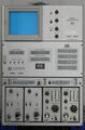
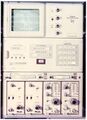
Front view of the system. The Mainframe and the plugins have remote/local switches
-
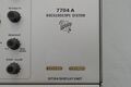
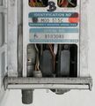
Tag indicating the modification
-
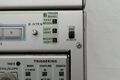
Remote/local switch on the lower section of the DPO
-
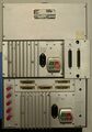
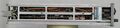
Rear view of the system
-
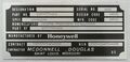
Tag added by Honeywell - indicates the later usage of this specific mainframe
-
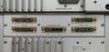
The additional connectors for remote control
-
The additional connectors for remote control (rear view)
-
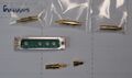
Replacements for the remote control connectors are still available in 2024
-
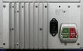
The switch to turn off the control illumination was removed.The Mod 515C needs a permanent 5V supply.
-
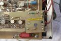
Additional connector board on the power supply
-
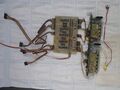
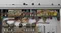
Most boards of the Mod 515C modification
-
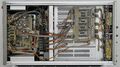
Overview on the additional boards in the lower section of the mainframe
-
The modified mode switches.
-
Mod 515C horizontal mode switch assembly. The lights work independently from the switches.
-
Mod 515C horizontal mode switch assembly. The lights work independently from the switches.
-
Mod 515C vertical mode switch assembly. The lights work independently from the switches.
-
Mod 515C vertical mode switch assembly. The lights work independently from the switches.
-
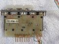
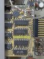
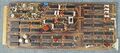
The main logic board of the Mod 515C
-
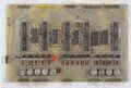
The main logic board of the Mod 515C
-
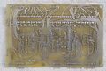
The main logic board of the Mod 515C
-
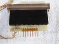
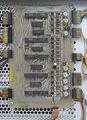
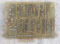
The serial receiver board
-
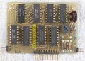
The serial receiver board
-
The serial receiver board
-
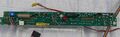
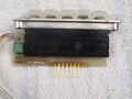
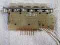
The Mod 515C calibrator board
-
Additional coax connectors of the plugin interfaces
-
Additional coax connectors of the plugin interfaces


P7001
The only modification to the P7001 was done on the z-axis/front panel pcb. A switch allowed to change to a longer timeout period for the external computer.
-
Z-Axis/Frontpanel pcb with additional switch and timing resistor
-
Z-Axis/Frontpanel pcb with additional switch and timing resistor


7A16A Mod 515D Plugin
The 7A16A Mod 515D adds the ability to remotely operate the Bandwith, Polarity and Position functions of the plugin.
Pinout of the remote connectors for the vertical plugins
| Pin | Function | Input Type | Range | Description |
|---|---|---|---|---|
| Coax #1 | Polarity | Digital | 0 or 5V, TTL compatible | +5V => +Up 0V => invert open => +Up |
| Coax #2 | Bandwith | Digital | 0 or 5V, TTL compatible | +5V => Full 0V => 20MHz open => Full |
| Coax #3 | Position | Analog | 0...5V | +5V => max upward 0V => max downward open => center |
| 5 Single Pins | Device Code | See Table below | ||
| Coax #4 | n.C. | |||
-
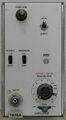
Front view of a 7A16A plugin with Mod 515D
-
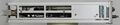
Left side
-
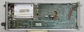
Right side
-
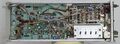
Top side
-
Closeup of serial number and Mod 515D sticker


7B71 Mod 515C Plugin
The 7B71 Mod 515C adds the ability to remotely operate the triggering level, the position & delay time, the magnifier setting and the trigger-modes. The modified 7B71 timebase can be configured as a delaying or as a delayed timebase.
Pinout of the remote connectors for the horizontal plugins
| Pin | Function | Input Type | Range | Description |
|---|---|---|---|---|
| Coax #1 | Trigger Level | Analog | 0...5V | +5V => max 0V => min open => center |
| Coax #2 | Delay Time Mult. | Analog | 0...5V | +5V => max 0V => min open => center |
| Coax #3 | Position | Analog | 0...5V | +5V => max 0V => min open => center |
| 5 Single Pins | Device Code | See Table below | ||
| Coax #4 | Trigger & Mag. | 8-Bit serial | TTL-Compatible | Bit 8: Mag Bit 7: Trig Slope Bit 6+5: Trig Coupl. Bit 4+3: Trig Mode Bit 2+1: Trig Source |
-
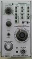
Front view of a 7B71 plugin with Mod 515C
-
Left side
-
Right side
-
Top side
-
Closeup of serial number and Mod 515C sticker


Device Code Matrix on the 5 rear Remote Connectors
The single contacts of each connector are grounded in different patterns to provide electrical identification to the computer.
| Connector | Single Pin #1 | Single Pin #2 | Single Pin #3 | Single Pin #4 | Single Pin #5 |
|---|---|---|---|---|---|
| Left vertical plugin | Open (n.C.) | GND | GND | GND | GND |
| Right vertical plugin | GND | Open (n.C.) | GND | GND | GND |
| Mainframe | GND | GND | Open (n.C.) | GND | GND |
| A horizontal plugin | GND | GND | GND | Open (n.C.) | GND |
| B horizontal plugin | GND | GND | GND | GND | Open (n.C.) |
Field of Application
Some details of the modification indicate that the WP1000AF system was developed either specifically for or in close consultation with Honeywell. Honeywell did some additional, but minor modifications to the system. The feet were modified so that the device could be fixed in place. They also added a cable tie holder and a tag to the back of the unit. The result got the Honeywell part-number 10066273-101 and the NSN number 6625-01-060-4390. The pictures on this page show such a device. Honeywell most likely used one of their own type of computer systems to control the DPO.
The contractors name and the contract number (see picture below) indicate that this specific instrument was involved in the development of the F15 aircraft project. And this external page: Michael J. Gooding, H. W. Sweatt Award reveals that a WP1000AF system was used in the Test Environment (TITE) for the F15 Tactical Electronic Warfare System (TEWS).
Parts of the Honeywell 10066273-101 bundle
| NSN Number | Component part number | Description | Manufacturer |
|---|---|---|---|
| 5365-01-053-8742 | 10057922-101 | Spacer, plate | Honeywell |
| 5365-01-052-9612 | 10057922-102 | Spacer, plate | Honeywell |
| 6625-01-034-4833 | WP1000AF | Oscilloscope | Tektronix |
| TY24M | Cable tie | Thomas & Betts | |
| TC5342A | Cable tie holder | Thomas & Betts | |
| MS24693C50 | Screw | Military Standards | |
| 33A1-13-484-1 | Documentation | Ordnance Corps | |
| 10063681-222 | Honeywell | ||
| 5310-01-082-3879 | 10057921-102 | Nut | Honeywell |
-

Replaced foot
-
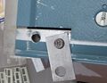
Replaced foot
-
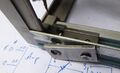
Replaced foot
-
Tag added by Honeywell - indicates the later usage of this mainframe
-
A picture (of a picture) containing a WP1000AF system in the 1970ies


