S-53: Difference between revisions
No edit summary |
("compatible with" links improved) |
||
| Line 4: | Line 4: | ||
image=S53-crop.jpg | | image=S53-crop.jpg | | ||
caption=S-53 head | | caption=S-53 head | | ||
series=[[ | series=[[3S2]], [[7S11]], [[7S12]] Sampling Plugins | | ||
years=? – ? | | years=? – ? | | ||
manuals= | manuals= | ||
| Line 13: | Line 13: | ||
}} | }} | ||
The Tektronix S-53 '''Trigger Recognizer''' is essentially the entire trigger circuit of an oscilloscope. | The Tektronix S-53 '''Trigger Recognizer''' is essentially the entire trigger circuit of an oscilloscope. | ||
amplifier before the tunnel diode. | The S-53 uses tunnel diode triggering with an amplifier before the tunnel diode. | ||
The signal first passes through a compensated NPN differential amplifier, Q10 and Q12, which provides | The signal first passes through a compensated NPN differential amplifier, Q10 and Q12, which provides | ||
an adjustable trigger offset voltage and trigger polarity selection. Switching diodes CR6 and CR8 are | an adjustable trigger offset voltage and trigger polarity selection. Switching diodes CR6 and CR8 are | ||
used for selecting the trigger polarity. The differential amplifier (i.e., phase splitter) generates | used for selecting the trigger polarity. The differential amplifier (i.e., phase splitter) generates | ||
both phases, inverted and | both phases, inverted and non-inverted. Depending on the position of the trigger polarity switch, one | ||
or the other of the phases is shunted by 200 Ω resistor. The two signals are buffered by common-base | or the other of the phases is shunted by 200 Ω resistor. The two signals are buffered by common-base | ||
amplifiers Q20 and Q22, whose collector currents are summed. R25 sets up a bias current on trigger | amplifiers Q20 and Q22, whose collector currents are summed. R25 sets up a bias current on trigger | ||
| Line 27: | Line 26: | ||
==Specifications== | ==Specifications== | ||
{{BeginSpecs}} | |||
{{Spec | Bandwidth | 1 GHz }} | |||
{{Spec | Input impedance | 50 Ω [[BNC connector]] }} | |||
{{Spec | Jitter | max. 15 ps or less (from input signal to trigger-out) }} | |||
{{Spec | Trigger-out signal | 1 V into 50 Ω with 600 mV/ns slew rate }} | |||
{{EndSpecs}} | |||
==Pictures== | ==Pictures== | ||
Revision as of 08:51, 17 July 2014

The Tektronix S-53 Trigger Recognizer is essentially the entire trigger circuit of an oscilloscope.
The S-53 uses tunnel diode triggering with an amplifier before the tunnel diode.
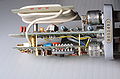
The signal first passes through a compensated NPN differential amplifier, Q10 and Q12, which provides an adjustable trigger offset voltage and trigger polarity selection. Switching diodes CR6 and CR8 are used for selecting the trigger polarity. The differential amplifier (i.e., phase splitter) generates both phases, inverted and non-inverted. Depending on the position of the trigger polarity switch, one or the other of the phases is shunted by 200 Ω resistor. The two signals are buffered by common-base amplifiers Q20 and Q22, whose collector currents are summed. R25 sets up a bias current on trigger tunnel diode CR25. The extra current from Q20 or Q22 pushes CR25 over its peak current, and it switches to the high voltage state.
Specifications
Key Specifications
| Bandwidth | 1 GHz |
|---|---|
| Input impedance | 50 Ω BNC connector |
| Jitter | max. 15 ps or less (from input signal to trigger-out) |
| Trigger-out signal | 1 V into 50 Ω with 600 mV/ns slew rate |
Pictures
-

-

-
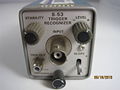
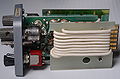
Front
-
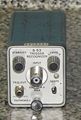
Front
-
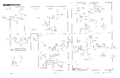
Schematic
-
-
-
-
-


