6R1: Difference between revisions
(one section per board) |
No edit summary |
||
| Line 16: | Line 16: | ||
boards in total. | boards in total. | ||
* | *Board A: COUNTER (6R1 has four of these) | ||
* | *Board B: DIVIDE BY 1,2,5 | ||
* | *Board C: MASTER GATE | ||
* | *Board D: SIGNAL COMPARATOR (6R1 has two of these) | ||
* | *Board E: VOLTMETER | ||
* | *Board F: UPPER LIMIT NO-GO | ||
* | *Board G: LOWER LIMIT NO-GO | ||
* | *Board H: LIGHT LIMIT DRIVER | ||
* | *Board I: DIVIDE BY 10 | ||
* | *Board J: ANALOG DISPLAY | ||
* | *Board K: 0% ZONE | ||
* | *Board L: MEMORY (6R1 has two of these) | ||
When a 6R1 is used in a 567 with a [[3T77]], the horizontal sweep signal is | When a 6R1 is used in a 567 with a [[3T77]], the horizontal sweep signal is | ||
| Line 38: | Line 38: | ||
to pin 7 of the 0% zone card. | to pin 7 of the 0% zone card. | ||
== | == Board K: 0% ZONE == | ||
The primary purpose if the 0% ZONE circuit is to produce | The primary purpose if the 0% ZONE circuit is to produce | ||
a signal that instructs the memory circuits to sample and hold the voltages at their | a signal that instructs the memory circuits to sample and hold the voltages at their | ||
| Line 59: | Line 59: | ||
is the logical complement of the +0% signal, generated by common-emitter inverter Q64. | is the logical complement of the +0% signal, generated by common-emitter inverter Q64. | ||
== | == Board L: MEMORY == | ||
The 6R1 contains two MEMORY | The 6R1 contains two MEMORY boards, one for vertical input A and one for vertical input B. | ||
Each MEMORY card contains two sample and hold circuits. | Each MEMORY card contains two sample and hold circuits. | ||
The main purpose of the MEMORY card is to sample and hold its vertical signal during the | The main purpose of the MEMORY card is to sample and hold its vertical signal during the | ||
| Line 115: | Line 115: | ||
the +GATE signal goes down to 0V. That turns off Q3 and | the +GATE signal goes down to 0V. That turns off Q3 and | ||
returns D13 and D23 to the original low-voltage state. | returns D13 and D23 to the original low-voltage state. | ||
== Board A: COUNTER (6R1 has four of these) == | |||
Each COUNTER board contains four flip-flops and functions as one | |||
digit of a decimal counter. Since the 6R1 has a four-digit decimal | |||
counter, it has four COUNTER boards. These boards have two functions | |||
aside from counting. First, they contain the NPN transistors that | |||
drive the Nixie tubes of the digital readout. Second, each COUNTER | |||
board contains a simple digital-to-analog converter (DAC) that produces | |||
a voltage proportional to the current count. This STAIRCASE voltage is | |||
used by the UPPER and LOWER LIMIT NO-GO boards. | |||
== Board B: DIVIDE BY 1,2,5 == | |||
== Board C: MASTER GATE == | |||
== Board D: SIGNAL COMPARATOR (6R1 has two of these) == | |||
== Board E: VOLTMETER == | |||
== Board F: UPPER LIMIT NO-GO == | |||
== Board G: LOWER LIMIT NO-GO == | |||
== Board H: LIGHT LIMIT DRIVER == | |||
== Board I: DIVIDE BY 10 == | |||
== Board J: ANALOG DISPLAY == | |||
[http://w140.com/tek_6r1_schem.pdf 6R1 Schematics] | [http://w140.com/tek_6r1_schem.pdf 6R1 Schematics] | ||
Revision as of 20:46, 9 June 2010
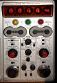
The Tektronix Type 6R1 is a plug-in for the 567 oscilloscope. It was later replaced by the 6R1A. The 6R1 provides digital readout of time and voltage measurements on waveforms. The 6R1 (and the 567 in general) is oriented toward sampling measurements. The basic building blocks of the 6R1 are a counter and comparators. To digitize analog voltages, the counter and comparator are used as a ramp-compare ADC.
The 6R1 does not contain any integrated circuits. Its logic in implemented using discrete bipolar transistors, vacuum tubes, and tunnel diodes. Most of the digital signals within the 6R1 use 0V to represented a "0" and 20V to represent a "1". Flip-flops (bistable multivibrators) are implemented in the 6R1 using the classic cross-coupled transistor pair. The counter is composed of several of these flip-flop subcircuits, as are various other state machines in the 6R1. All of the active circuitry of the 6R1 is on small plug-in printed circuit boards. There are twelve different boards labeled A through L. The 6R1 contains more than one of some of the boards, seventeen boards in total.
- Board A: COUNTER (6R1 has four of these)
- Board B: DIVIDE BY 1,2,5
- Board C: MASTER GATE
- Board D: SIGNAL COMPARATOR (6R1 has two of these)
- Board E: VOLTMETER
- Board F: UPPER LIMIT NO-GO
- Board G: LOWER LIMIT NO-GO
- Board H: LIGHT LIMIT DRIVER
- Board I: DIVIDE BY 10
- Board J: ANALOG DISPLAY
- Board K: 0% ZONE
- Board L: MEMORY (6R1 has two of these)
When a 6R1 is used in a 567 with a 3T77, the horizontal sweep signal is generated by the staircase generator circuit in the 3T77. From R184 in the 3T77's staircase generator, the sweep signal is sent to the horizontal amplifier circuit of the 3T77, where it enters the sweep mode switch. Assuming that the sweep mode switch is in the NORMAL or SINGLE DISPLAY positions, the sweep signal is sent out through R318 to pin 20 on P22, the connector on the rear of the 3T77. The 567 carries the signal to pin 8 on P32 of the 6R1. Within the 6R1, the sweep signal is carried to pin 7 of the 0% zone card.
Board K: 0% ZONE
The primary purpose if the 0% ZONE circuit is to produce a signal that instructs the memory circuits to sample and hold the voltages at their inputs during the first cm of the sweep. On the 0% ZONE card, the sweep signal which arrives on pin 7 is buffered by V43, a Nuvistor cathode-follower, and the buffered sweep signal is sent out from pin 10 of the 0% ZONE card. This is a secondary feature of the 0% zone card. To accomplish its main purpose, the 0% ZONE card compares the buffered sweep voltage with a fixed voltage, putting D43, a 2mA tunnel diode, into the high voltage state whenever the sweep signal is above about 5 V. Since the sweep signal goes from 0 V to 50 V for a complete sweep, 5V corresponds to a point 1 major division from the left edge of the display. The +GATE signal goes high at the beginning of each sweep and returns low at the end of each sweep. The +0% OUT signal is high only during the first cm of the sweep. The logic is +GATE AND NOT (SWEEP > 5V). When the sweep starts, Q23 pulls the top leg of R54 high, and since Q54 is off at the point, the voltage on the bottom leg of R54 also rises, raising the voltage at the base of buffer transistor Q63, which raises the +0% output. When the sweep voltage reaches 5V and the Q54 turns on, the voltage on the bottom leg of R54 drops to near 0 V. The buffer Q63 follows, and the +0% output falls. The -0% output signal is the logical complement of the +0% signal, generated by common-emitter inverter Q64.
Board L: MEMORY
The 6R1 contains two MEMORY boards, one for vertical input A and one for vertical input B. Each MEMORY card contains two sample and hold circuits. The main purpose of the MEMORY card is to sample and hold its vertical signal during the 0% and 100% zones. One sampler on the MEMORY card captures the the signal voltage during the 0% zone. The other captures the signal voltage during the 100% zone. The input to both of the the samplers is the output signal of the vertical plug-in. Since this is a relatively slow-changing signal with a relatively long sampling time, each sampler circuit is simply a sampling gate (also known as a transmission gate or analog switch) feeding a 1uF holding capacitor, the voltage on which is buffered by a Nuvistor cathode follower.
The 0% sample and hold circuit gets its sampling signal from the 0% ZONE card. When the 0% ZONE card detects that the sweep is within the 0% zone, the +0% zone signal is +20 V and the -0% zone signal is 0 V. This turns off Q63 and Q73. About 3.2mA flows from the +125 V supply and splits approximately equally between the left diode path (D61 and D71) and the right diode path (D62 and D72). With both paths conducting, the bridge is "on" and the holding capacitor (C80) voltage converges to the vertical signal voltage. When the 0% zone card detects the the sweep has left the 0% zone, the +0% zone signal goes to 0 V and the -0% zone signal goes to 20 V. This turns on Q63 and Q73, which act as emitter-followers, lowering the voltage at the top of the sampling bridge and raising the voltage at the bottom of the sampling bridge, reverse-biasing the diodes in the bridge. With D62 and D72 reverse-biased, current cannot flow through R80. Assuming that the grid current of V83 is zero, whatever charge is on the holding capacitor at the end of the sampling pulse is trapped on the the capacitor until the next sampling pulse. (V_cap = Q_cap / C).
The 100% zone sample and hold circuit gets its sampling signals from the 100% zone detector circuit which is also on the MEMORY card. The purpose of the 100% zone detector circuit is to generate a logic signal that is true when the sweep is within the 100% zone. The horizontal position of the 100% zone is variable using the "A 100% ZONE SET" and "B 100% ZONE SET" controls on the front of the 6R1. One pin 12, the MEMORY card get the +GATE signal, which is high while the timing unit (3T77, for example) is sweeping. Between sweeps, the +GATE signal is low, 0V, which turns off Q3. With Q3 off, Q13 and Q23 have no collector current, so D13 and D23 have no current. When the sweep starts, the +GATE signal goes to +20V, and the emitter voltage of Q3 follows. Tunnel diodes D13 and D23 operate in a bistable mode. When the sweep ramp starts, both diodes are in their low-voltage state. When the sweep enters the left edge of the 100% zone, D23 switches to the high-voltage state, while D13 remains in the low-voltage state. This causes the base voltage of Q33 to rise, turning Q33 off, and it causes the base voltage of Q43 to fall, turning Q43 off. This turns on the sampling gate, as discussed above for the 0% sample and hold circuit. When the sweep ramp reaches a voltages the corresponds to the right edge of the 100% zone, D13 switches to the high-voltage state, turning on Q14, which turns off the sampling gate. The sampling gate connects the vertical input signal to the holding capacitor when D23 is in the high-voltage state and D13 is in the low-voltage state. At the end of the sweep, the +GATE signal goes down to 0V. That turns off Q3 and returns D13 and D23 to the original low-voltage state.
Board A: COUNTER (6R1 has four of these)
Each COUNTER board contains four flip-flops and functions as one digit of a decimal counter. Since the 6R1 has a four-digit decimal counter, it has four COUNTER boards. These boards have two functions aside from counting. First, they contain the NPN transistors that drive the Nixie tubes of the digital readout. Second, each COUNTER board contains a simple digital-to-analog converter (DAC) that produces a voltage proportional to the current count. This STAIRCASE voltage is used by the UPPER and LOWER LIMIT NO-GO boards.
Board B: DIVIDE BY 1,2,5
Board C: MASTER GATE
Board D: SIGNAL COMPARATOR (6R1 has two of these)
Board E: VOLTMETER
Board F: UPPER LIMIT NO-GO
Board G: LOWER LIMIT NO-GO
Board H: LIGHT LIMIT DRIVER
Board I: DIVIDE BY 10
Board J: ANALOG DISPLAY
-
Front
-

Connector J33
-

Connector J34


