Repairing 7000-series plug-in sockets: Difference between revisions
No edit summary |
No edit summary |
||
| Line 1: | Line 1: | ||
A common problem with 7000-series scopes | A common problem with 7000-series scopes are the sockets in the mainframe that accept the | ||
plug- | plug-ins. The fingers of the connector are springy metal. The fingers are supported by a flat piece | ||
of plastic on either side of connector. This piece of plastic tends to crack, which causes the connector | of plastic on either side of connector. This piece of plastic tends to crack, which causes the connector | ||
fingers to be unsupported, which causes bad electrical connection with the plug-in, which typically | fingers to be unsupported, which causes bad electrical connection with the plug-in, which typically | ||
| Line 10: | Line 10: | ||
Bought the nice 7504 Ebay 112036180730 recently, which after some cleaning was | Bought the nice 7504 Ebay 112036180730 recently, which after some cleaning was | ||
nearly as new from its cosmetic appearance, but as many of these had the connector | nearly as new from its cosmetic appearance, but as many of these had the connector | ||
problem. This made the operation on all | problem. This made the operation on all plug-in places useless with random uncorrelated | ||
faults. | faults. | ||
</blockquote> | </blockquote> | ||
| Line 17: | Line 17: | ||
are not the problem, but the deterioration of the plastic covers on the sides of these | are not the problem, but the deterioration of the plastic covers on the sides of these | ||
connectors. If they loose their strength, the contact pressure is gone. In order to apply | connectors. If they loose their strength, the contact pressure is gone. In order to apply | ||
the procedure below, the plastic covers must still be | the procedure below, the plastic covers must still be in place and not broken. Sorry for | ||
bad pictures, I was in a hurry. | bad pictures, I was in a hurry. | ||
</blockquote> | </blockquote> | ||
| Line 28: | Line 28: | ||
I had boards of what we call Pertinax, synthetic resin paper, of 5 mm strength, the width | I had boards of what we call Pertinax, synthetic resin paper, of 5 mm strength, the width | ||
of the boards was 75 mm and it may not be much more - if you cut it, it must be shorter | of the boards was 75 mm and it may not be much more - if you cut it, it must be shorter | ||
than the connector itself, have a look at the other side. I had to cut eight pieces of 23 mm. | than the connector itself, have a look at the other side at the plug-in itself. I had to | ||
cut eight pieces of 23 mm. | |||
</blockquote> | </blockquote> | ||
<blockquote> | <blockquote> | ||
For the raw material see picture 0 below. It surely is possible to use a different non conductive | For the raw material see picture 0 below. It surely is possible to use a different non | ||
stiff material instead. | conductive stiff material instead. | ||
</blockquote> | </blockquote> | ||
<blockquote> | <blockquote> | ||
| Line 38: | Line 39: | ||
four-plugin unit. On one place the distance was only 4 mm, but the piece was easy to | four-plugin unit. On one place the distance was only 4 mm, but the piece was easy to | ||
file down. At some points additional rasping is necessary due to wires or components, | file down. At some points additional rasping is necessary due to wires or components, | ||
but most of the gaps are clear of these. | but most of the gaps are clear of these. The Pertinax is easily treated. | ||
</blockquote> | </blockquote> | ||
<blockquote> | <blockquote> | ||
| Line 47: | Line 48: | ||
On the outside, the two remaining pieces must be fixed to the connector side in a different | On the outside, the two remaining pieces must be fixed to the connector side in a different | ||
way. I used two metal bars for this and carefully made screw holes to the edges of the | way. I used two metal bars for this and carefully made screw holes to the edges of the | ||
connectors. See picture 1 with | connectors. See picture 1 with plug-in; here you can see also why the strips may not | ||
have the same length as the connector. | have the same length as the connector. | ||
</blockquote> | </blockquote> | ||
<blockquote> | <blockquote> | ||
It was useful to take the main board off the instrument to perform this work | It was useful to take the main board off the instrument to perform this work, but I did not | ||
remove the fixed wiring. It took few hours to do this, but was worth the effort. The | remove the fixed wiring. It took few hours to do this, but was worth the effort. The plug-ins | ||
have a tight fit now and the scope is working perfectly well. | have a tight fit now and the scope is working perfectly well. | ||
</blockquote> | </blockquote> | ||
Revision as of 10:41, 2 October 2016
A common problem with 7000-series scopes are the sockets in the mainframe that accept the plug-ins. The fingers of the connector are springy metal. The fingers are supported by a flat piece of plastic on either side of connector. This piece of plastic tends to crack, which causes the connector fingers to be unsupported, which causes bad electrical connection with the plug-in, which typically results in erratic failures that sometimes come and go when the plug-in is pushed or pulled slightly.
Andreas Schubert describes his experience with a 7504 that had this problem:
Bought the nice 7504 Ebay 112036180730 recently, which after some cleaning was nearly as new from its cosmetic appearance, but as many of these had the connector problem. This made the operation on all plug-in places useless with random uncorrelated faults.
Had a close inspection, because I wanted to give this to a friend. The contacts itself are not the problem, but the deterioration of the plastic covers on the sides of these connectors. If they loose their strength, the contact pressure is gone. In order to apply the procedure below, the plastic covers must still be in place and not broken. Sorry for bad pictures, I was in a hurry.
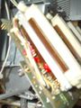
On this 7505 model and surely on (most or all) other 7000 series main connector boards you see small additional piggyback circuit boards. I found the distance of these to the connectors to be fairly constant about 5 mm.
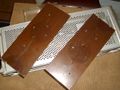
I had boards of what we call Pertinax, synthetic resin paper, of 5 mm strength, the width of the boards was 75 mm and it may not be much more - if you cut it, it must be shorter than the connector itself, have a look at the other side at the plug-in itself. I had to cut eight pieces of 23 mm.
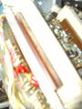
For the raw material see picture 0 below. It surely is possible to use a different non conductive stiff material instead.
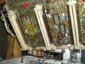
Six bits fit quite nicely in the six gaps between piggy back boards and connectors of a four-plugin unit. On one place the distance was only 4 mm, but the piece was easy to file down. At some points additional rasping is necessary due to wires or components, but most of the gaps are clear of these. The Pertinax is easily treated.
These make a good pressure to the long sides of the connectors and are adjusted nicely perpendicular if inserted in the gaps and pushed completely down to the main board.
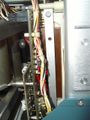
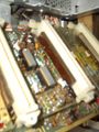
On the outside, the two remaining pieces must be fixed to the connector side in a different way. I used two metal bars for this and carefully made screw holes to the edges of the connectors. See picture 1 with plug-in; here you can see also why the strips may not have the same length as the connector.
It was useful to take the main board off the instrument to perform this work, but I did not remove the fixed wiring. It took few hours to do this, but was worth the effort. The plug-ins have a tight fit now and the scope is working perfectly well.
-
0
-
1
-
2
-
3
-
4
-
5


