7B92A/Repairs: Difference between revisions
Jump to navigation
Jump to search
(Not complete.) |
(please sign first-person info) |
||
| Line 1: | Line 1: | ||
I picked up a barn find and the 7B92A looked in good shape until I spotted U244 - a dual op amp MC1458N 8 DIP | I picked up a barn find and the 7B92A looked in good shape until I spotted U244 - a dual op amp MC1458N 8 DIP: | ||
<gallery> | <gallery> | ||
| Line 6: | Line 6: | ||
From the service manual: | From the service manual: | ||
<blockquote> | |||
Internal Source (SN B070000-above). When the Delayed Trigger Generator is using an internal trigger | |||
signal, the internal trigger signal from the vertical channel of the oscilloscope is connected to the Delayed Trigger | |||
Generator through J250. Signals above 30 kilohertz are coupled through C246 to pin 14 of U274 . (Pins 13 and 14 of | |||
U274 are internally connected.) Signals below 30 kilohertz are connected to amplifier U244 through R257. The output | |||
of amplifier U244 is coupled, along with the offset from the LEVEL control, to pin 1 of U274. | |||
</blockquote> | |||
are connected to amplifier U244 through R257. The output | --[[User:Qfissler]] 15 Oct 2023 | ||
Revision as of 01:33, 16 October 2023
I picked up a barn find and the 7B92A looked in good shape until I spotted U244 - a dual op amp MC1458N 8 DIP:
-
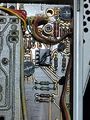
Cracked U244

From the service manual:
Internal Source (SN B070000-above). When the Delayed Trigger Generator is using an internal trigger signal, the internal trigger signal from the vertical channel of the oscilloscope is connected to the Delayed Trigger Generator through J250. Signals above 30 kilohertz are coupled through C246 to pin 14 of U274 . (Pins 13 and 14 of U274 are internally connected.) Signals below 30 kilohertz are connected to amplifier U244 through R257. The output of amplifier U244 is coupled, along with the offset from the LEVEL control, to pin 1 of U274.
--User:Qfissler 15 Oct 2023