PS503/Repairs: Difference between revisions
Jump to navigation
Jump to search
No edit summary |
|||
| Line 3: | Line 3: | ||
==PS503A Manual== | ==PS503A Manual== | ||
There is an error in the circuit drawing: All amplifiers are connected to +5 V or -5 V. In fact they are connected to the +6.2 V or -6.2 V | There is an error in the circuit drawing: All amplifiers are connected to +5 V or -5 V. In fact they are connected to the +6.2 V or -6.2 V supply. | ||
==PS503A: Instable Output/Output voltage is decreasing with time== | ==PS503A: Instable Output/Output voltage is decreasing with time== | ||
Revision as of 04:51, 21 February 2024
- Tektronix PS503A Power Supply Restoration by NFM @ YouTube
PS503A Manual
There is an error in the circuit drawing: All amplifiers are connected to +5 V or -5 V. In fact they are connected to the +6.2 V or -6.2 V supply.
PS503A: Instable Output/Output voltage is decreasing with time
The output is instable (±100 mV) and is decreasing with time. The faulty part was C34 (4.7 µF/50 V). C34 stabilises the reference voltage. Measuring C34 with an RLC-meter shows no fault: 5.0 µF and a serial resistance of 5 Ω. The faulty behaviour of C34 can only be seen by applying a DC voltage (see picture).
C34 is shorted by the output-on button. So, replacing C34 with a tantalum capacitor is not recommended.
Pictures
-
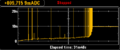
DC current thru C34 (12 V / 10 mA limit)
