506: Difference between revisions
No edit summary |
No edit summary |
||
| Line 10: | Line 10: | ||
one for the CRT cathode voltage and one for the intensification voltage, | one for the CRT cathode voltage and one for the intensification voltage, | ||
which is applied to a second grid in the CRT. | which is applied to a second grid in the CRT. | ||
The 506 uses the [[T5033|T5033-31-1]] CRT, which has P31 [[phosphor]]. | |||
The total accelerating voltage is 3.5kV. | |||
The calibrator signal is produced by shaping mains frequency | The calibrator signal is produced by shaping mains frequency | ||
| Line 26: | Line 28: | ||
Output tubes are used for all of the regulated supply voltages except the -12.2V supply, | Output tubes are used for all of the regulated supply voltages except the -12.2V supply, | ||
which uses a [[2N1529]] germanium PNP transistor. | which uses a [[2N1529]] germanium PNP transistor. | ||
* [http://w140.com/tek_506_Manual_070-445_Aug_1964.pdf Tektronix 506 Manual (PDF)] | * [http://w140.com/tek_506_Manual_070-445_Aug_1964.pdf Tektronix 506 Manual (PDF)] | ||
Revision as of 14:34, 25 May 2014
The Tektronix Type 506 is an oscilloscope with bandwidth above 20MHz that uses 2-series or 3-series horizontal plug-ins but special high-speed vertical plug-ins, the 9A1, and 9A2. Like the scopes in the 560 Series, the 506 mainframe contains neither vertical nor horizontal amplifiers; the plug-ins directly drive the CRT deflection plates.
The CRT does not use post-deflection acceleration. The CRT circuit uses two 5642 high-voltage rectifier tubes, one for the CRT cathode voltage and one for the intensification voltage, which is applied to a second grid in the CRT. The 506 uses the T5033-31-1 CRT, which has P31 phosphor. The total accelerating voltage is 3.5kV.
The calibrator signal is produced by shaping mains frequency into a square wave. It is not just a simple clipping circuit. To speed up the edges, positive feedback is used. A cross-connected triode and pentode form a schmitt trigger. The input of the shaping circuit is the cathode of the triode and the output is the cathode of the pentode, which drives a voltage divider whose tap is selected by the front panel calibrator rotary switch.
The power supply is fairly typical of Tektronix scopes of the period. An OG3 tube establishes a -82V reference voltage in the -100V power supply section. The -100V supply is then used as the reference voltage for the other power supply sections. Output tubes are used for all of the regulated supply voltages except the -12.2V supply, which uses a 2N1529 germanium PNP transistor.
-

-
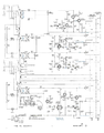
Power Supply
-
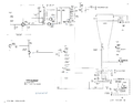
CRT Circuit
-
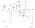
Calibrator
-
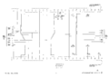
Interconnecting Sockets


