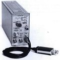
SG504
The Tektronix SG504 is a levelled sinewave generator plug-in for the TM500 system.
Key Specifications
| Frequency range | 50 kHz or 6 MHz (Ref), 245 MHz to 550 MHz (Lo), 495 MHz to 1050 MHz (Hi) |
|---|---|
| Output amplitude | 0.5 Vp-p to at least 4 Vp-p, flat to within ±4% |
| Monitor output | 0.3 Vp-p into 50 Ω |
| FM input | ±9 V into 50 kΩ (DC to 100 kHz) produces ±0.05% to ±0.4% deviation depending on frequency |
Output Head
The SG504 is usually found on Ebay without the output head (015-0282-00). David Partridge did an excellent teardown and reverse engineering of the output head and sells kits to make new heads.
It's fairly easy to use that schematic to make a new level head that fits in a standard BNC Pomona box since its function is really just a 250 MHz to 1050 MHz temperature compensated power meter with 50 Ω feed-thru. See the pictures for an example.
As of April 2016, Ebay seller "ancelb" is selling SG504 leveling (output) heads that are specified to perform much better than the original Tektronix heads. See photo below.
There is an open source project to replace the output head at hackaday.io.
Videos
SG504 Repair and Frustraton from a stubborn unit by Zenwizard Studios @ YouTube
Service Notes
- Lo Band Harmonic Distortion (Usually 3 dB or Higher) - Make sure pin diodes on R.F. Board are as close as possible to the board.
- Signal Output Good and Level Light is Off (at 650-695 MHz) - Suspect J39 is shorted.
- Harmonic Distortion:
- 1. Make sure leads on 070 and Q120 are straight and short.
- 2. Be sure C126 and C128 are centered on etched capacitors.
- 3. Suspect chip caps which are heat sensitive and tend to crack.
- Reference Oscillator Out Of Specifications (50 kHz or 6 MHz) - Suspect T200 or T205.
- Adjusting for Harmonics - Excessive Harmonic levels at Low End of Low Band can be helped by adjusting C125. Adjusting C125 would lower the harmonic level but it would reduce the upper frequency on the Low Band at which time unlevelling would occur.
- Adjustment Effects - Spreading L125 decreases upper levelling frequency and decreases harmonics at low end.
- Spreading L126 has approx. equal effects - Increased harmonic level and increased upper levelling frequency. (Opposite effect of L125).
- Spreading L128 has same effect as L126 but affects upper levelling frequency more.
- Solution - Adjust C125 to set 2nd Harmonic for -26dB, compress L125, spread L126 approx. 1/16 ", spread L128 approx. 1/8". Reset C125 to begin unlevelling at first arrow past stop at upper end of dial. The worst the 2nd Harmonic should be now approx. -28dB .
- L48 should always be completely compressed.
- L45 may help harmonics by really playing with it.
- SG504 HARMONIC DISTORTION AND LEVELING IMPROVEMENTS
- The following changes have been made to improve performance and reliability of the SG504 from S/N B011080:
- 1. The two coax cables (P/N 175-0323-00) connecting the output of the low and high band oscillator cavities (A40) to the two input buffer transistors (A2070 , A2Q120) have been shortened from 3.0 inches to 2.687 inches. This improves the 550 MHz high band harmonics about 2dB. The new cable part number is 175-1870-00.
- 2. A 33pf capacitor, A2C1761 (P/N 281-0819-00) has been installed from the base of A2Q170 to ground as shown in Figure 1 below. This change improves output levelling at 1 GHz.
- The above changes should be incorporated in any A2 RF boards with P/N 670-4038-00.
- The following changes have been made to improve performance and reliability of the SG504 from S/N B011080:
Pictures
-
-
-
-
With output head (catalog picture)
-
Home-made output head
-
Late Revision Front Panel with LED Frequency Readout
-
SG504 head being produced and sold on Ebay by seller "ancelb"
-
SG504 in TM515 with other TM500 gear
-
Output head
-
Output head
-
Output head
-
Output head
-
Output head
-
Output head
-
Output head
-
Output head
-
Service Note Fig.1


